AC Filter Capacitors for Inverters and UPS: What IEC 61071 Asks For
In this article
- The capacitor in the filter
- Which standard: IEC 61071, not IEC 60831 or IEC 60252
- The stresses a filter capacitor must survive
- Calculating the current with harmonic content
- From losses to hot-spot temperature
- Construction features that address these stresses
- Checklist for selecting a filter capacitor
- Conclusion
- HYDRA AC filter capacitors and documents
- References
A PWM inverter needs an output or grid-side filter, and the capacitor in that filter carries much of the stress. The HYDRA catalogue lists AC filter capacitors for damping of undesirable voltage spikes during the switching of power semiconductors, for UPS systems and for wind power [10], and IEC 61071 names filtering among the applications of capacitors for power electronics [1].
Such a capacitor looks like a power factor correction capacitor, but it falls under a different standard. This article explains which standard applies, and how to estimate current and losses before choosing a part.
Key takeaways
- An AC filter capacitor in an inverter or UPS falls under IEC 61071, not under the PFC standard IEC 60831-1.
- Because current grows with frequency, a few volts at the switching frequency can drive more current than the full mains voltage.
- A capacitor selected from the 50 Hz current alone would be undersized in current by a factor of more than three.
The capacitor in the filter
In a sine-wave filter, an inductor L1 in series with the inverter output and a capacitor Cf across the output form a low-pass LC filter. A reference design by Texas Instruments notes that for many rectifiers a higher-order LCL filter, with a second inductor on the grid side, typically provides sufficient harmonic attenuation, and that its resonance has to be designed with care [5]. The same design limits the reactive power absorbed by the filter capacitor to 3.5 %, checks that the resonant frequency is an order of magnitude above the line frequency and less than half the switching frequency, and adds a passive damping resistor of the same order of magnitude as the impedance of Cf at resonance [5].
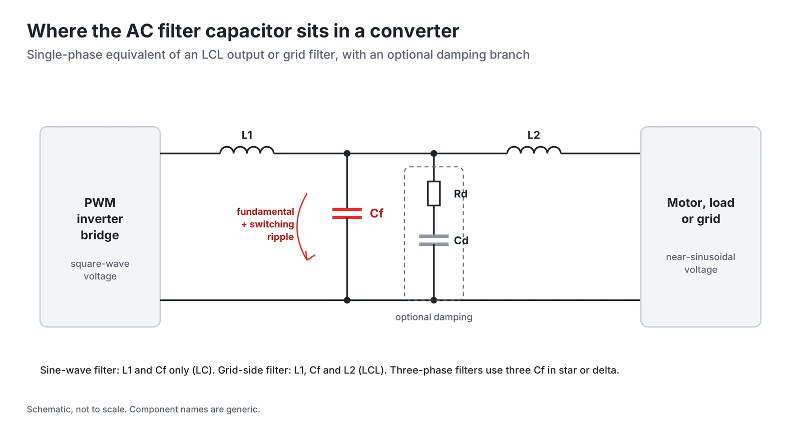
For the capacitor this means current at the fundamental and at higher frequencies, for as long as the converter runs. IEC 61071 notes that at high frequency the capacitor losses are predominantly due to losses in connections, contacts and electrodes [2].
Which standard: IEC 61071, not IEC 60831 or IEC 60252
IEC 61071, Capacitors for power electronics, second edition, was published in August 2017 and replaced the first edition of 2007 [1]. It applies to capacitors for power electronics applications whose operating frequency is usually up to 15 kHz, while the pulse frequencies may be up to 5 to 10 times the operating frequency. It distinguishes between AC and DC capacitors and covers applications such as overvoltage protection, DC and filtering, switching circuits and energy storage [1]. The European adoption, EN IEC 61071:2025 (August 2025), supersedes EN 61071:2007 [3].
The scope explicitly excludes neighbouring families, which have their own standards [1]:
| Capacitor type | Standard |
|---|---|
| Self-healing shunt capacitors up to 1000 V AC (PFC) | IEC 60831-1 and -2 |
| Motor capacitors | IEC 60252-1 and -2 |
| Fluorescent and discharge lamp capacitors | IEC 61048, IEC 61049 |
| Radio interference suppression | IEC 60384-14 |
| Railway applications | IEC 61881 |
IEC 60831-1 covers capacitor units and banks intended to be used, particularly, for power-factor correction of AC power systems up to 1000 V and 15 Hz to 60 Hz [4]. A filter capacitor in a power electronic system works at operating frequencies that IEC 61071 puts usually up to 15 kHz [1]. The table of contents of IEC 61071 lists, among others, the surge discharge test, the thermal stability test, the self-healing test, the resonance frequency measurement, the endurance test and the destruction test [1].
One definition deserves attention. IEC 61071 defines the rated AC voltage UN as the maximum operating peak recurrent voltage of either polarity of a reversing type waveform for which the capacitor has been designed, and notes that it is not an r.m.s. value [2]. Before comparing a datasheet with an application, check how the datasheet states its AC rating and compare it with the true peak of the waveform, harmonics included.
The stresses a filter capacitor must survive
RMS current. IEC 61071 defines Imax as the maximum r.m.s. current for continuous operation [2]. In the filter example below it is dominated by high-frequency components.
Peak current. IEC 61071 defines the maximum peak current as the maximum repetitive peak current that can occur during continuous operation, and the maximum surge current as a peak non-repetitive current induced by switching or any other disturbance of the system, allowed a limited number of times [2].
Voltage with harmonic content. Harmonics add to the peak voltage. In the illustrative example below, a 230 V RMS fundamental (325 V peak) plus four small harmonics can reach up to about 344 V peak if all peaks coincide, a worst-case sum that is still 6 % above the fundamental peak.
Hot-spot temperature. The standard defines the hotspot temperature as the highest temperature present inside the capacitor dielectric [2]. Losses from all frequency components raise it, and HYDRA states the life expectancy of its AC filter capacitors at a hot spot below 70 °C, or below 85 °C for EAB [10].
Overvoltage. The non-recurrent surge voltage Us is a peak voltage induced by a switching or any other disturbance of the system, allowed a limited number of times and for durations shorter than the basic period [2].
Calculating the current with harmonic content
Each frequency component of the capacitor voltage drives its own current, I = 2πf × C × U, which follows from the capacitive reactance 1/(2πfC) [7]. By Parseval's theorem the RMS values of the components add as a root sum of squares [6]:
Un is the RMS voltage of the component at frequency fn. Because current grows with frequency, a few volts at the switching frequency can drive more current than the full mains voltage.
Consider an illustrative 50 µF capacitor with 230 V at 50 Hz, 4.6 V at 250 Hz, 3.45 V at 350 Hz, 4 V at 8 kHz and 1.5 V at 16 kHz. The voltage values are assumptions chosen for the example, not measurements. The fundamental gives 2π × 50 × 50 µF × 230 V = 3.6 A. The 8 kHz component gives 2π × 8000 × 50 µF × 4 V = 10.1 A, and the 16 kHz component 7.5 A. The total is 13.1 A RMS, while the RMS voltage barely changes from 230 V.
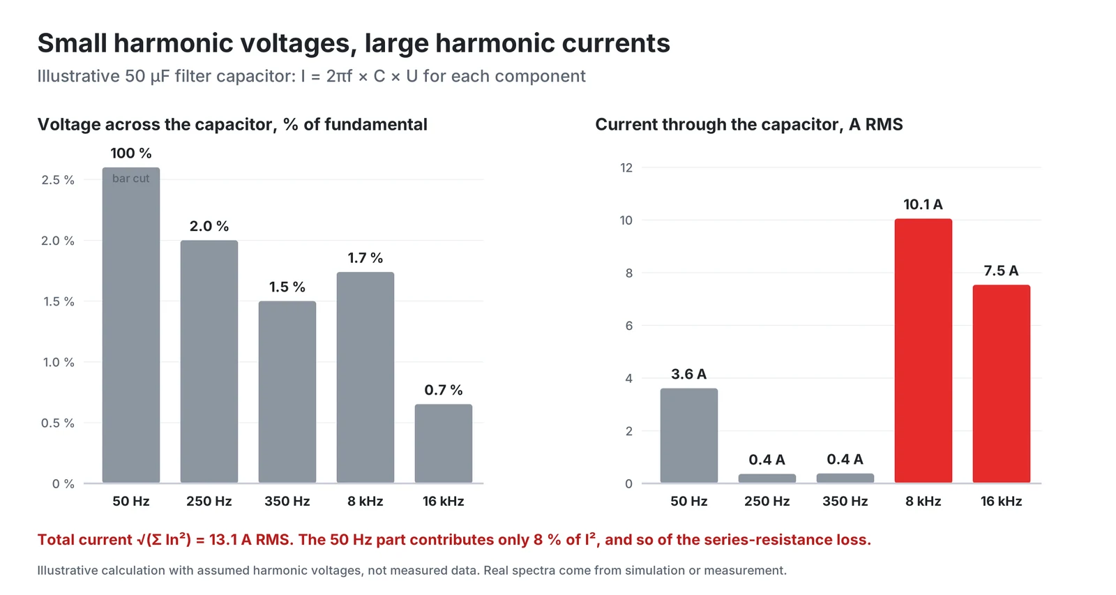
A capacitor selected from the 50 Hz current alone would be undersized in current by a factor of more than three. In practice the spectrum comes from simulation or prototype measurement, and the result is compared with Imax at the expected cooling-air temperature.
From losses to hot-spot temperature
IEC 61071 writes the loss factor of a capacitor as the sum of a dielectric loss factor and the series-resistance term Rs ωC [2]. The losses can therefore be split into a dielectric part and a Joule part, calculated for each frequency and summed. The hot spot then follows from the cooling-air temperature and the thermal resistance Rth:
Applied to the example above with assumed values of tan δ₀ = 2 × 10⁻⁴ and Rs = 2 mΩ, the dielectric loss is about 0.18 W, almost all of it at 50 Hz, and the Joule loss is 13.1² × 0.002 = 0.34 W, of which only 0.03 W comes from the fundamental. The harmonics dominate the Joule loss. Where the datasheet gives the frequency dependence of the series resistance, use it. The hot spot then follows from the datasheet thermal resistance and the real cooling conditions.
Construction features that address these stresses
Current capability is limited not only by the dielectric. IEC 61071 attributes the capacitor losses at high frequency predominantly to connections, contacts and electrodes [2], and a film supplier describes the mechanical contact between the end-spraying layer and the metallized film as an extremely important factor for a good dissipation factor and a high pulse capability [9]. Three features target that path.
Profile metallization. A film supplier describes the heavy edge as the classical solution to enable a stable and low resistive contact to the end-spray, and states that one of the two films in a wound capacitor must always have good self-healing behaviour using a high resistive area, typically 1/3 low and 2/3 high resistivity over the film width [8]. A defined resistance profile lets the designer optimise tan δ, self-healing and breakdown voltage [8].
Wave-cut edges. According to the same supplier, a contact edge in wave-cut form combined with an optimised winding offset can significantly improve the contact of the end-spraying layer, and a wave cut at the free margin edge spreads mechanical stresses and reduces the risk at high operating temperatures or high currents [9].
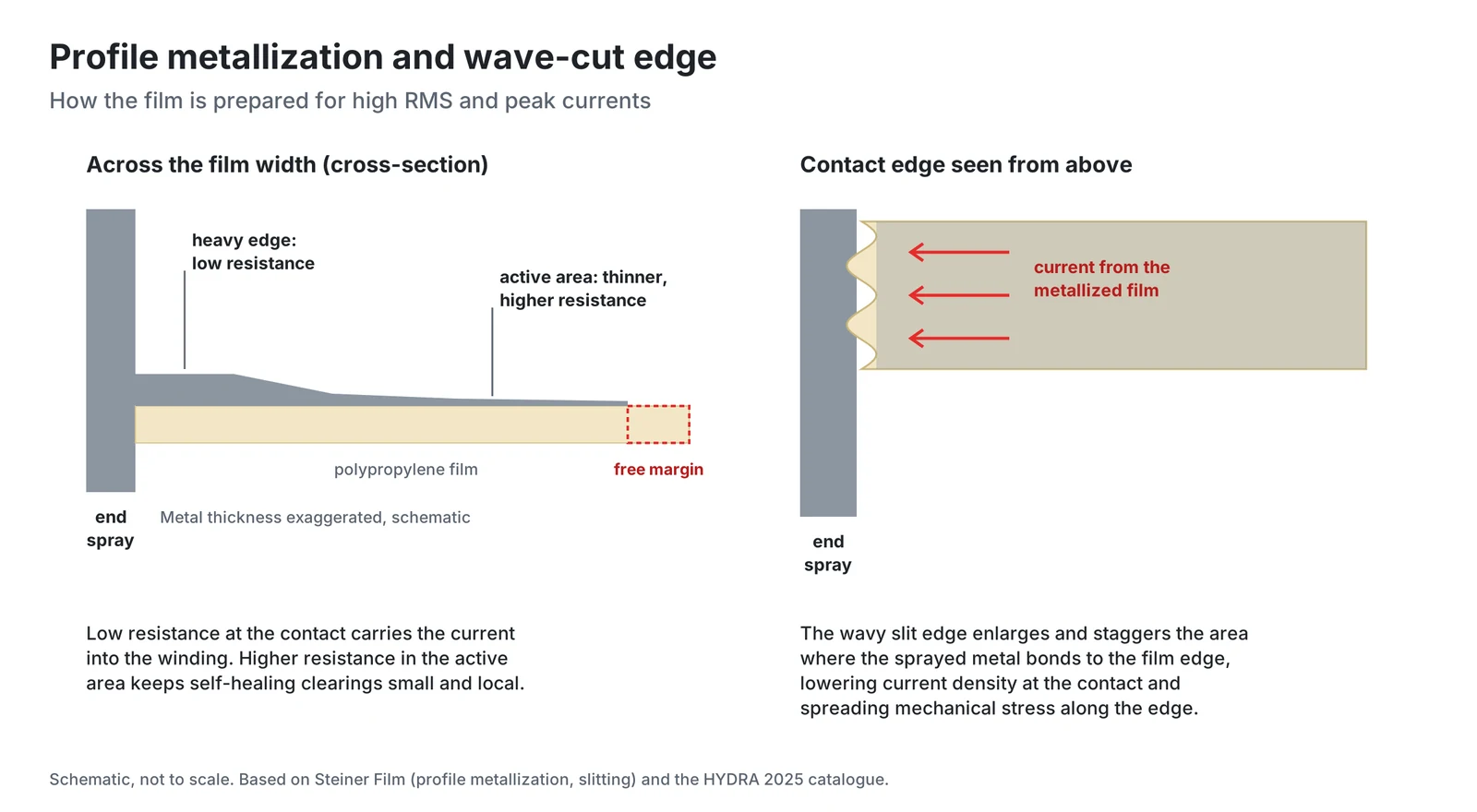
Filling and overpressure interrupter. HYDRA fills its AC filter capacitors with vegetable oil or soft resin for best thermal performance and fits a built-in overpressure interrupter for safe operation in case of an internal failure [10]. HYDRA motor capacitor datasheets describe the same principle in detail: gas generation and temperature rise build up internal pressure, the can expands and the disconnector separates the capacitor from the mains [11].
HYDRA's AC filter series EAB, EBB, ERB and ECB combine these features: profile metallization for overvoltage reliability, wave-cut film for RMS and peak current, vegetable oil or soft-resin filling, and a built-in overpressure interrupter. The 2025 catalogue lists rated voltages from 420 V to 1400 V AC, rated currents up to 80 A, single-phase and three-phase versions, and a life expectancy of 100 000 h at a hot spot below 70 °C (below 85 °C for EAB), with compliance to IEC 61071 (2017-08) Ed. 2.0 and UL 810 (file E201956).
Checklist for selecting a filter capacitor
- Specify the capacitor to IEC 61071, not only to IEC 60831.
- Obtain the voltage spectrum across the capacitor, switching sidebands included.
- Calculate the RMS current as a root sum of squares and compare it with Imax.
- Check the true peak voltage against the rated AC voltage, a peak value in IEC 61071.
- Check repetitive peak and surge current.
- Calculate losses per frequency and the hot spot, and compare it with the hot spot at which life is specified.
Conclusion
An AC filter capacitor in an inverter or UPS falls under IEC 61071, not under the PFC standard IEC 60831-1. In the illustrative example, small harmonic voltages drive most of its current and Joule losses, so it should be selected from the full spectrum, checked against a peak voltage rating and a hot-spot limit, and built for high current at the contact. The final selection should always be confirmed with the capacitor manufacturer's datasheets and application engineers for the specific operating conditions.
HYDRA AC filter capacitors and documents
HYDRA AC filter capacitors use profile-metallized polypropylene film with a wave-cut design, vegetable oil or soft-resin filling and a built-in overpressure interrupter. The 2025 catalogue lists them as compliant with IEC 61071 (2017-08) Ed. 2.0 and UL 810 (file E201956), with a life expectancy of 100 000 h.
| Series | Connection | Rated voltage AC | Rated current | Life condition |
|---|---|---|---|---|
| EAB MKP | 1-phase | 420 to 1200 V | 6 to 16 A | Hot spot below 85 °C |
| EBB MKP | 1-phase | 420 to 1350 V | 40 to 80 A | Hot spot below 70 °C |
| ERB DPM | 1 to 3-phase, star or delta | 640 to 1400 V | Up to 80 A | Hot spot below 70 °C |
| ECB DPM | 3-phase, delta | 640 to 1400 V | Up to 16 A | Hot spot below 70 °C |
Further documents:
- HYDRA capacitors catalogue 2025 (PDF), with the AC filter, DC link, PFC and motor capacitor ranges
- HYDRA product overview
- Documents and certificates: UL, ISO 9001, RoHS and REACH
- Contact HYDRA for application support
References
- IEC 61071:2017, Capacitors for power electronics, edition 2.0, 2017-08. Free IEC preview with the foreword, Clause 1 Scope and the table of contents.
- IEC 61071:2017, definitions 3.17 to 3.40. Free sample (iTeh).
- STN EN IEC 61071:2025 (EN IEC 61071:2025), free preview by ÚNMS SR, European foreword.
- IEC 60831-1:2014, Shunt power capacitors of the self-healing type for AC systems having a rated voltage up to and including 1000 V, Part 1: General, edition 3.0. Free IEC preview, Clause 1 Scope.
- Texas Instruments, TIDUEZ0A, 11-kW bidirectional three-phase ANPC based on GaN reference design, LCL filter design section.
- C. Guo, Z. Xin, J. Han, L. Hu, B. Lu, Review of the calculation of DC-link capacitor current, Frontiers in Energy Research 11:1240755, 2023, open access, equation 34 (Parseval's theorem).
- OpenStax, University Physics Volume 2, 15.2 Simple AC Circuits, equation 15.3.
- Steiner Film GmbH, Profile Metallization.
- Steiner Film GmbH, Slitting Technologies.
- HYDRA a.s., Hydra Capacitors catalogue 2025, AC Filter Capacitors (PDF).
- HYDRA a.s., Motor capacitors series 500, datasheet (PDF), section Safety.
Products in this article
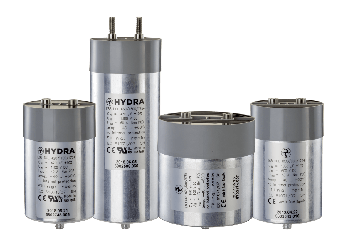
DC link & power electronics
Check stockAsk a HYDRA engineer
Send us your application data and our engineers will help you choose the right film capacitor. HYDRA has made film capacitors since 1899, with production in Jičín (Czech Republic) and Da Nang (Vietnam).
Ask an engineerCheck stock