Replacing Electrolytic Capacitors with Film in the DC Link: A Practical Checklist
In this article
The DC link of motor drives, solar inverters and other converters is often built from aluminium electrolytic capacitors. A 2023 review by Guo et al. notes that converter systems for driving motors mostly use them, and Wang and Blaabjerg describe them as offering the highest energy density and the lowest cost per joule. Metallized polypropylene film capacitors are the alternative that Wang and Blaabjerg describe as well balanced in terms of cost and ESR for high-voltage applications, for example above 500 V.
The answer is rarely a one-for-one swap of microfarads. Wang and Blaabjerg show that in high ripple current applications an electrolytic bank needs more capacitance than the voltage ripple alone requires, while a film solution can stay at the capacitance that the voltage ripple specification sets. This article explains why, and gives a checklist for deciding when the change makes sense.
Key takeaways
- Replacing electrolytic capacitors with film in the DC link is not a matter of matching microfarads.
- Cost: film costs more per joule but less per ampere, so it wins where ripple current, not energy, sets the size.
- Where hold-up energy dominates, electrolytics or a hybrid of both technologies remain the economical choice.
Start from the criterion that sets the capacitance
The capacitance of a DC link is set by whichever of three requirements is the hardest to meet:
- Ripple current. The converter draws an AC ripple current from the DC link, and the capacitors must carry its RMS value. Guo et al. list absorbing the current ripple on the DC bus among the main roles of DC-link capacitors.
- Voltage ripple. Wang and Blaabjerg define C1 as the minimum capacitance that fulfils the voltage ripple specification. Guo et al. add stabilising the DC-side voltage.
- Stored energy. Some systems must provide energy during a hold-up time (Wang and Blaabjerg), and the capacitance must then store enough energy between the nominal and the minimum permitted voltage.
Wang and Blaabjerg show that the ripple current capability of DC-link capacitors is approximately proportional to their capacitance. In high ripple current applications an electrolytic bank with the capacitance C1 cannot sustain the ripple current stress because of its low A/µF, so the capacitance is increased to C2. The capacitance on the schematic is then set by the ripple current, not by the voltage ripple.
That is where film becomes interesting. In the same comparison the film solution stays at C1, and Wang and Blaabjerg put the cost of film capacitors per ampere of ripple current at about one third of that of electrolytics. When stored energy is the dominant requirement, the picture is different: electrolytics have the highest energy density and the lowest cost per joule. A hybrid of both technologies is another option, as in the 250 kW inverter example with a 40 mF electrolytic bank and a 2 mF film capacitor that Wang and Blaabjerg cite.

How the two technologies compare
The table summarises the main differences qualitatively, following Wang and Blaabjerg (text, Fig. 4 and Table I) and the HYDRA DC link datasheet. Individual series differ, and the datasheets of the parts under consideration are always the final reference.
| Property | Aluminium electrolytic | Metallized polypropylene film |
|---|---|---|
| Ripple current per microfarad | Low | High |
| ESR | Relatively high | Low, 0.8 to 4.1 mΩ in HYDRA EGB and EBB DCL |
| Voltage | Intermediate in the Wang and Blaabjerg comparison | Well balanced above about 500 V, up to 1500 V DC in one HYDRA DCL part |
| Failure modes | Open circuit, short circuit, wear out by electrolyte vaporization | Open circuit (typical), short circuit with resistance, wear out by gradual capacitance loss |
| Cost per joule stored | Lower | Higher |
| Cost per ampere of ripple | Higher | About one third of electrolytic |
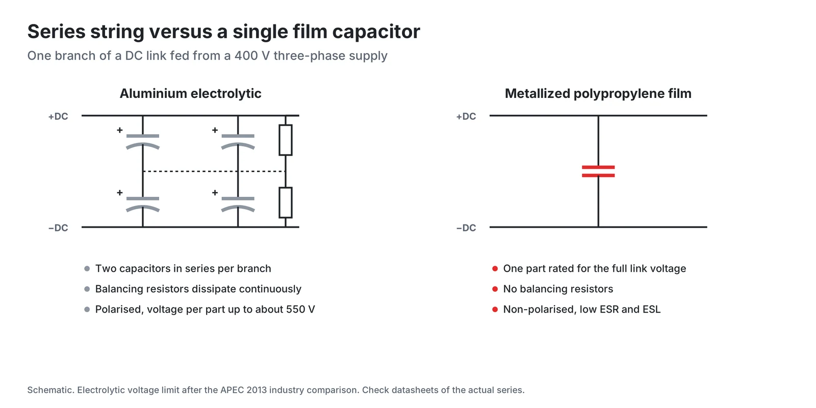
Two rows decide most projects. Voltage: HYDRA EGB and EBB DCL capacitors are rated from 700 to 1500 V DC, and the HYDRA datasheet states that no series connection of capacitors is necessary. Cost: film costs more per joule but less per ampere, so it wins where ripple current, not energy, sets the size.
The ageing mechanisms are different as well. Wang and Blaabjerg name electrolyte vaporization as the major wear-out mechanism of small electrolytic capacitors. Guo et al., citing Kolar and Round, state that the expected life of an electrolytic capacitor doubles for every 10 °C reduction relative to the rated temperature. In film capacitors, initial dielectric breakdowns at weak points are cleared by self-healing, and the capacitance is gradually reduced until end of life. Wang and Blaabjerg list voltage, temperature, ripple current and humidity as their critical stressors.
Three quick calculations before the decision
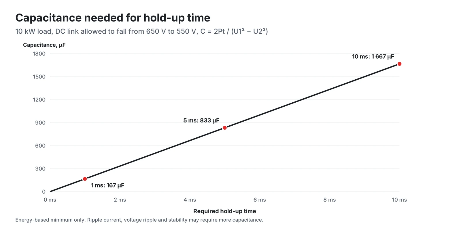
1. Is the capacitance set by stored energy? The energy stored in a capacitor is ½ C U² (OpenStax University Physics, equation 8.10), so the energy it delivers when its voltage falls from U₁ to U₂ is ½ C (U₁² - U₂²). For a hold-up time t at power P the minimum capacitance is therefore:
As an example, take a 10 kW drive whose DC link may fall from 650 V to 550 V. Every millisecond of hold-up then requires about 167 µF, and 10 ms requires about 1.7 mF. At that size the energy density and cost per joule of electrolytics, or a hybrid solution, become attractive. A drive without a hold-up requirement can be sized for ripple current and voltage ripple, which is where film is strongest.
2. Does the voltage require series connection? Compare the highest link voltage, including mains tolerance, regeneration and switching overshoot, with the rated voltage of a single capacitor. HYDRA DC link film capacitors cover 700 to 1500 V DC in one part.
3. Is the ripple current the real driver? Compare the RMS ripple current of the application, from simulation or from the analytical methods reviewed by Guo et al. (including Kolar and Round), with the ripple current rating of the existing electrolytic bank. If the bank has far more capacitance than the voltage ripple requires, it was sized for current, and a film design will need fewer microfarads.
Checklist for the change
- Identify the sizing criterion. Determine whether ripple current, voltage ripple or stored energy sets the capacitance today. Film is a natural candidate only in the first two cases.
- Calculate the ripple current spectrum. Guo et al. review simulation, RMS analysis and spectral analysis methods for the DC-link capacitor current. Compare the result with the maximum RMS current per part, which the HYDRA datasheet states for every type.
- Check the voltage ripple with the new capacitance. Less capacitance means more voltage ripple. Confirm that the control loop, the modulation and the semiconductor voltage margins accept it.
- Recheck resonance. Guo et al. describe resonance between the DC-link capacitors and the DC bus inductor, characterised by the ratio of the PWM carrier frequency to the resonant frequency of the LC circuit. A change of capacitance changes that resonant frequency, so recheck it with the DC choke, the cables and the input filter.
- Adjust precharge and inrush limiting. Recheck the precharge circuit for the new capacitance and respect the surge and repetitive peak current ratings of the film capacitor, which the HYDRA datasheet lists for every type.
- Rate the voltage for the whole link. Include mains overvoltage, regenerative braking and switching overshoot, and check the rating at the case temperature expected in the application.
- Use the low ESL. The switching overshoot across a semiconductor is the stray inductance multiplied by di/dt (Shao, Chalmers University of Technology, equation 2.1). With an assumed loop inductance of 20 nH and a di/dt of 2 kA/µs, the overshoot is 40 V. The HYDRA DCL datasheet gives an inductance below 50 nH per part.
- Plan the thermal path. HYDRA DCL capacitors are rated for a case temperature of -25 °C to 60 °C (70 °C max.). Keep the capacitors away from heat sinks and resistors.
- Compare total cost, not part cost. Include balancing resistors, the number of parts, busbar complexity, assembly time and the replacement interval over the warranty period.
Conclusion
Replacing electrolytic capacitors with film in the DC link is not a matter of matching microfarads. It pays off when ripple current, not stored energy, sets the size of the bank: film carries more current per microfarad, costs less per ampere of ripple current and has no electrolyte to evaporate. Where hold-up energy dominates, electrolytics or a hybrid of both technologies remain the economical choice. Start from the sizing criterion, recheck voltage ripple, resonance, precharge and layout, and compare total cost over the life of the product.
This article gives general design guidance. The final selection should always be confirmed with the capacitor manufacturer's datasheets and application engineers for the specific series and operating conditions.
HYDRA DC link capacitors and documents
HYDRA EGB DCL and EBB DCL DC link capacitors use self-healing metallized polypropylene film with a dry resin filling, so there is no liquid electrolyte. They are designed to IEC 61071 and listed under UL file E201956. The datasheet states the following ratings.
| Parameter | EGB DCL and EBB DCL |
|---|---|
| Rated voltage | 700 to 1500 V DC |
| Capacitance | 120 to 2800 µF |
| Series resistance | 0.8 to 4.1 mΩ |
| Life expectancy | 100 000 h at rated voltage and hot spot below 70 °C |
| Operating case temperature | -25 °C to 60 °C (70 °C max.) |
Further documents:
- DC link capacitors datasheet (PDF)
- HYDRA capacitors catalogue 2025 (PDF), with the DC link, AC filter, PFC and motor capacitor ranges
- HYDRA product overview
- Documents and certificates: UL, ISO 9001, RoHS and REACH
- Contact HYDRA for application support
References
- H. Wang, F. Blaabjerg, Reliability of Capacitors for DC-Link Applications in Power Electronic Converters, An Overview, IEEE Transactions on Industry Applications, vol. 50, no. 5, pp. 3569-3578, 2014, DOI 10.1109/TIA.2014.2308357. Free version of record (Aalborg University), sections I to IV, Fig. 4, Fig. 5, Table I.
- C. Guo, Z. Xin, J. Han, L. Hu, B. Lu, Review of the calculation of DC-link capacitor current, Frontiers in Energy Research 11:1240755, 2023, open access (CC BY), sections 1, 2 and 4.1. It summarises J. W. Kolar, S. D. Round, Analytical calculation of the RMS current stress on the DC-link capacitor of voltage-PWM converter systems, IEE Proc. Electric Power Applications 153(4), 2006.
- OpenStax, University Physics Volume 2, 8.3 Energy Stored in a Capacitor, equation 8.10.
- Y. Shao, Improving the Efficiency of SiC-based Inverter in BEV by Selecting the Switching Slew Rate, Master's thesis, Chalmers University of Technology, 2024, section 2.1.1, equation 2.1.
- HYDRA a.s., DC link capacitors EGB DCL and EBB DCL, datasheet (PDF).
- IEC 61071:2017, Capacitors for power electronics, edition 2.0.
Products in this article
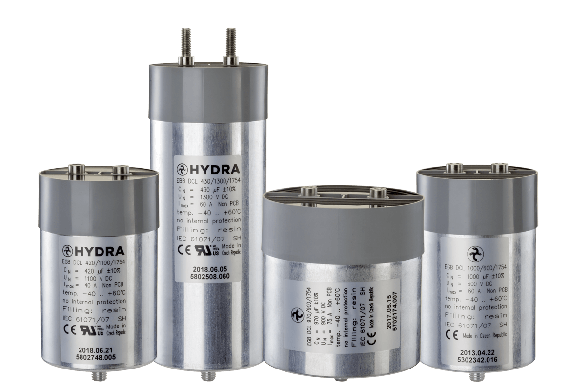
DC link & power electronics
Check stockAsk a HYDRA engineer
Send us your application data and our engineers will help you choose the right film capacitor. HYDRA has made film capacitors since 1899, with production in Jičín (Czech Republic) and Da Nang (Vietnam).
Ask an engineerCheck stock