DC-Link Film Capacitors for 800 V SiC Drives: Voltage, ESL and the 105 °C Barrier
In this article
The move from 400 V to 800 V battery platforms, together with silicon carbide (SiC) switches, changes what a DC-link capacitor has to do. The capacitor no longer only stores charge and absorbs ripple. It becomes part of the commutation loop of a switch with faster switching speeds than silicon devices, and the higher power density of SiC makes thermal management increasingly critical. Three questions follow: which voltage class the capacitor needs, how much inductance the loop can tolerate, and what happens to a polypropylene dielectric above about 105 °C.
The topic is clearly gaining attention. A search of the passive-components.eu archive for the exact phrase "800 V", repeated on 18 October 2026, returns 5 posts published in 2025 and 42 posts published in 2026 up to 6 October. Outside Europe the shift is visible in sales: according to a ResearchAndMarkets report, passenger car sales with 800 V architecture in China reached 840,000 in 2024, a penetration rate of 6.9 %, and the publisher expects more than 35 % by 2030. These are the publisher's claims.
An earlier article in this series covered how to size a film DC link when replacing electrolytics. This one assumes the capacitance is known and looks at voltage, inductance and temperature.
Key takeaways
- It becomes part of the commutation loop of a switch with faster switching speeds than silicon devices, and the higher power density of SiC makes thermal management increasingly critical.
- It needs a voltage class that covers the full-charge battery voltage of up to about 1000 V and the switching overshoot.
- And it needs a realistic thermal design, because standard polypropylene is limited to operating temperatures below 105 °C, and temperature and voltage together set the lifetime.
Why 800 V pushes the capacitor into the 900 to 1200 V classes
The nominal battery voltage is not the voltage the DC link sees. A Texas Instruments design guide notes that an 800 V EV can hold as much as 1000 V on a full charge, and selects a 1200 V breakdown for the transistor and diode of its precharge circuit. A published SiC reference design for an 800 V battery supports a DC-link voltage of up to 900 V. The film capacitor has to cover the same window, plus switching overshoot, for its whole life.
Mains-fed industrial drives arrive at similar numbers by a different route. The peak of a sinusoidal voltage is √2 times its RMS value (OpenStax, University Physics Volume 2, section 15.4), so the rectified line-to-line peak is about 566 V on a 400 V supply and about 976 V on a 690 V supply, before mains tolerance and regenerative braking are added.
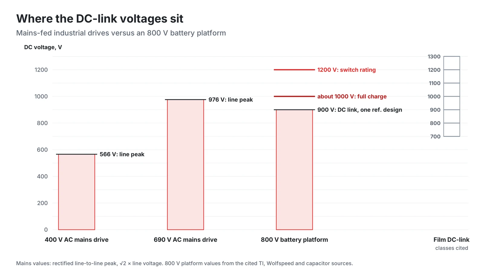
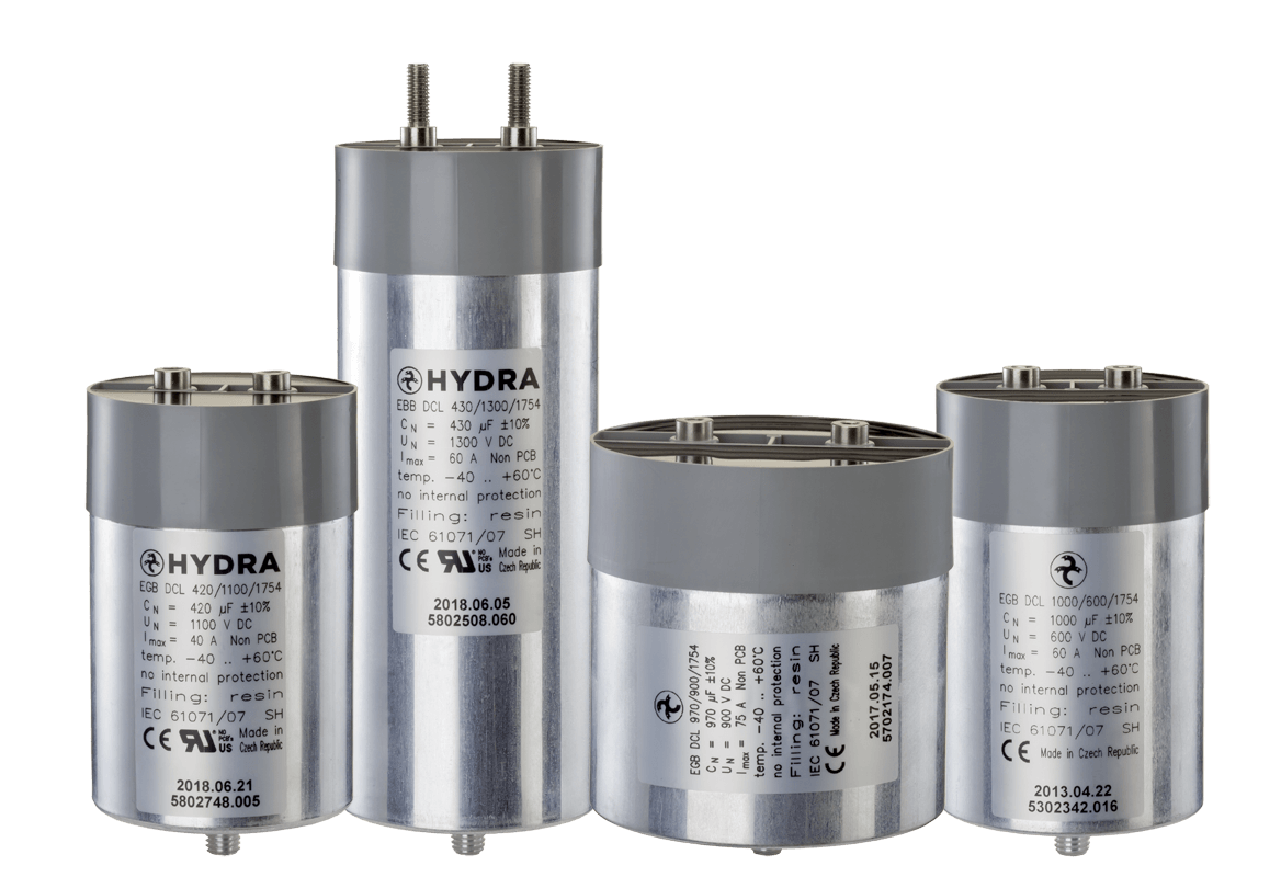
A film capacitor rated for the full link voltage avoids a series string. HYDRA's EGB DCL and EBB DCL datasheet lists "no series connections of capacitors necessary" among the features and covers rated voltages from 700 to 1500 V DC.
SiC speed turns ESL into a voltage problem
SiC switches change voltage and current much faster than silicon IGBTs. In one SiC inverter test at 800 V described in a Chalmers University of Technology thesis, the turn-off voltage slew rate settled at about 25 V/ns. Fast switching reduces losses, but the same thesis notes that higher switching speeds increase the voltage across the transistor at turn-off. The overshoot is caused by stray inductance, and the switch sees the DC-link voltage plus the inductive overshoot:
The loop inductance lies between the capacitors and the power-switching devices and includes the capacitor's equivalent series inductance (ESL), the busbar and the module. A worked example: with a loop inductance of 20 nH and a current slope of 10 kA/µs (10 A/ns), the overshoot is 20 × 10⁻⁹ × 10 × 10⁹ = 200 V. On a 900 V link this brings the switch to 1100 V, leaving only 100 V of margin to a 1200 V rating. At 30 nH the same slope uses up the whole 300 V of headroom. The di/dt values in Figure 2 are examples chosen for the calculation, not data for a specific device.
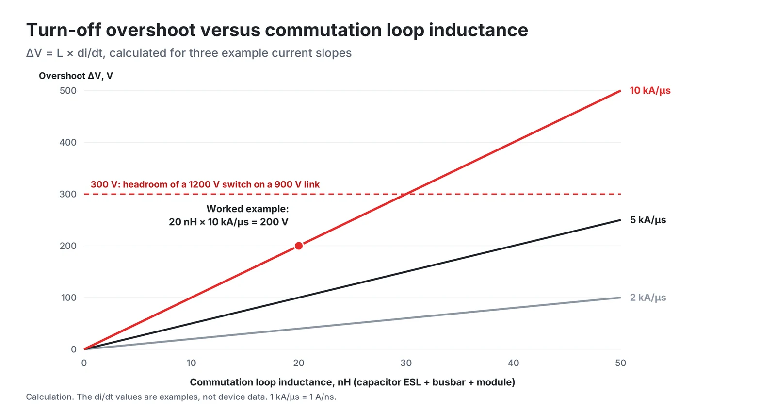
A 2026 overview in Electronic Design describes the same constraint: capacitors with high ESL may not effectively suppress the voltage spikes generated during fast switching events, so low-inductance capacitor designs are of primary importance in SiC inverters.
ESL also sets the frequency above which the DC-link capacitor stops behaving as a capacitor. The self-resonant frequency follows from the resonant angular frequency ω₀ = 1/√(LC) of an RLC circuit (OpenStax, section 15.5):
For an assumed 500 µF film capacitor with 30 nH, the resonant frequency is about 41 kHz. With 50 nH it falls to about 32 kHz. Above this frequency the inductive reactance Xₗ = ωL (OpenStax, section 15.3) dominates and rises with frequency, so the large film capacitor alone cannot supply the very fast edges of a SiC switching transition. This is the reason for the two design approaches below.
Busbar integration and film plus ceramic hybrids
The first approach removes inductance from the interconnection. A 2021 SAE paper from McMaster University describes a single integrated busbar connecting the DC-link capacitor, the high-voltage DC connector and the power module, with the stated aims of minimizing parasitic inductances, increasing power density and achieving a uniform current distribution across the capacitor cores.
The second approach adds small, low-inductance capacitors close to the switches. The Electronic Design overview states that for many EV SiC inverters the optimal solution is a hybrid that combines film capacitors with a cluster of ceramic capacitors. In that overview, multilayer ceramic capacitors offer very low ESR and ESL and are highly effective at the higher switching frequencies of SiC, while film capacitors provide low ESR and ESL with high ripple current capability.
Ripple current and ESR heating
According to the Electronic Design overview, the faster switching of SiC results in higher ripple current frequencies, and minimizing ESR is key to the capacitor's thermal stability. The loss in the series resistance is P = I² × R (OpenStax, section 9.5). As an example using values from HYDRA's 2019 DC-link datasheet, a 1100 V part with 480 µF has a maximum RMS current of 60 A and a series resistance of 1.5 mΩ. At its rated current it dissipates 60² × 0.0015 = 5.4 W. Twice the current would give four times the loss, 21.6 W. The actual loss at high frequency should be checked with the manufacturer for the real current spectrum.
The 105 °C barrier
Biaxially oriented polypropylene (BOPP) is the most commonly available commercial dielectric polymer. Metallized polypropylene film capacitors owe their most important reliability feature, self-healing, to the metallized electrode, and polypropylene has a loss factor about ten times lower than polyester. Its weakness is temperature. A 2025 paper in Nature Communications describes BOPP as limited to operating temperatures below 105 °C, notes rising demand for capacitors working at 150 °C and above, and reports an all-organic composite dielectric tested at 200 °C.
Other films are already used where it is hotter. Gallay notes that polyethylene naphthalate (PEN) up to 125 °C or polyphenylene sulfide (PPS) up to 150 °C are used in high-temperature applications.
The practical consequence is that the capacitor temperature and the voltage class must be chosen together. In Gallay's lifetime model, the speed of capacitance loss depends on temperature, voltage and humidity, and the required dielectric thickness is first calculated for the voltage and then adapted to the temperature profile.
Where HYDRA's DC-link capacitors fit
HYDRA's EGB DCL and EBB DCL capacitors are metallized polypropylene parts in aluminium cases with polyurethane or epoxy resin filling, compliant with IEC 61071 and UL file E201956. The 2019 datasheet lists 120 to 2800 µF, 700 to 1500 V DC, inductance below 50 nH and a life expectancy of 100,000 hours at rated voltage and a hot spot below 70 °C, together with series resistance from 0.8 to 4.1 mΩ and maximum RMS currents from 15 to 100 A per part.
The datasheet names DC-link and DC filter applications in industrial inverters for wind turbines, solar power and power drives, replacement of aluminium electrolytic capacitors and AC filters in UPS. The specified case temperature range is -25 to 60 °C, with 70 °C maximum, so they are not automotive traction parts. For 800 to 1000 V industrial drives, solar and storage converters, where the capacitor can be kept cool and a single part per voltage class is valued, the voltage and inductance discussion above applies directly.
Conclusion
An 800 V SiC platform asks three things of the DC-link film capacitor. It needs a voltage class that covers the full-charge battery voltage of up to about 1000 V and the switching overshoot. It needs a low ESL and a short, integrated busbar, because at several kA/µs each nanohenry costs volts of switch margin, and small ceramic capacitors close to the switches often take the fastest edges. And it needs a realistic thermal design, because standard polypropylene is limited to operating temperatures below 105 °C, and temperature and voltage together set the lifetime.
HYDRA DC-link capacitors and documents
HYDRA EGB DCL capacitors have terminals with an internal thread, and EBB DCL capacitors have stud terminals. Both are metallized polypropylene capacitors in an aluminium case with dry polyurethane or epoxy resin filling, rated to IEC 61071 and listed under UL file E201956. The datasheet gives an inductance below 50 nH and a life expectancy of 100,000 hours at rated voltage and a hot spot below 70 °C.
| Rated voltage Un | Surge voltage Us | Capacitance | Max. RMS current | Series resistance |
|---|---|---|---|---|
| 700 V DC | 1050 V DC | 280 to 2800 µF | 25 to 100 A | 0.8 to 2.5 mΩ |
| 900 V DC | 1350 V DC | 220 to 2500 µF | 25 to 100 A | 0.9 to 2.9 mΩ |
| 1100 V DC | 1650 V DC | 140 to 1500 µF | 20 to 100 A | 1.0 to 2.8 mΩ |
| 1300 V DC | 1950 V DC | 120 to 1150 µF | 15 to 80 A | 0.9 to 3.0 mΩ |
| 1500 V DC | 2250 V DC | 140 to 850 µF | 25 to 80 A | 1.2 to 4.1 mΩ |
Further documents:
- DC-link capacitors EGB DCL and EBB DCL datasheet (PDF), with the full product table
- HYDRA capacitors catalogue 2025 (PDF), with DC-link, AC filter, PFC and motor capacitors
- HYDRA products
- Documents and certificates: ISO 9001, RoHS and REACH
- Contact for other voltages and capacitance values
References
- T. Zeng et al., Enhancing energetic disorder in all-organic composite dielectrics for high-temperature capacitive energy storage, Nature Communications, 1 July 2025, DOI 10.1038/s41467-025-60741-1.
- H. Ansell, Helix, Reevaluating DC-Link Capacitors for SiC Inverters, Electronic Design, 30 June 2026.
- ResearchAndMarkets.com, New Energy Vehicle 800-1000V High-Voltage Architecture and Supply Chain Report 2025, Business Wire press release, 21 October 2025, via FinancialContent.
- Texas Instruments, TIDUF73, High-Voltage Passive Precharge With Overcurrent Protection Reference Design, design guide, section 2.2.2.1, September 2024.
- Y. Hu, Wolfspeed Enables Higher-Voltage Batteries for EV Systems, Power Systems Design, 4 January 2023.
- Y. Shao, Improving the Efficiency of SiC-based Inverter in BEV by Selecting the Switching Slew Rate for Optimisation of Switching Losses and Voltage Overshoot, Master's thesis, Chalmers University of Technology, 2024, sections 1.1, 2.1.1 and 5.
- Y. Wang, J. Mistry, P. Azer, B. Bilgin, Integrated Busbar Design for Stray Inductance and Volume Reduction in a High-Power SiC Traction Inverter, SAE Technical Paper 2021-01-0777, 6 April 2021, DOI 10.4271/2021-01-0777 (abstract).
- OpenStax, University Physics Volume 2, 9.5 Electrical Energy and Power, 15.3 RLC Series Circuits with AC, 15.4 Power in an AC Circuit and 15.5 Resonance in an AC Circuit. Rice University, CC BY 4.0.
- R. Gallay, Metallized Film Capacitor Lifetime Evaluation and Failure Mode Analysis, CERN-2015-003, p. 45, DOI 10.5170/CERN-2015-003.45. CERN Yellow Reports, CC BY 4.0.
- H. Wang, F. Blaabjerg, Reliability of Capacitors for DC-Link Applications in Power Electronic Converters: An Overview, IEEE Transactions on Industry Applications 50(5), 2014. Aalborg University repository.
- HYDRA a.s., HYDRA capacitors catalogue 2025, DC-Link Capacitors.
- HYDRA a.s., DC Link Capacitors EGB DCL/EBB DCL datasheet, edition 01/2019.
- passive-components.eu WordPress REST API, posts matching the exact phrase "800 V", count in the X-WP-Total header, accessed 18 October 2026.
Products in this article
DC link & power electronics
Check stockAsk a HYDRA engineer
Send us your application data and our engineers will help you choose the right film capacitor. HYDRA has made film capacitors since 1899, with production in Jičín (Czech Republic) and Da Nang (Vietnam).
Ask an engineerCheck stock