Choosing the Rated Voltage of a Motor Run Capacitor: Why the Working Voltage Exceeds the Mains
In this article
A permanent split capacitor (PSC) motor connected to a 230 V supply carries a run capacitor with a rated voltage well above 230 V. HYDRA's motor run capacitors, for example, are rated 400 V to 500 V AC in most series. The reason is that in normal operation the voltage across a run capacitor is above the supply voltage, so a capacitor chosen by the mains value alone would run above its rating.
This article explains where the extra voltage comes from, how large it typically is, what IEC 60252-1 asks the equipment designer to do about it, and how to measure the working voltage so that the rated voltage on the specification is based on data rather than habit.
Key takeaways
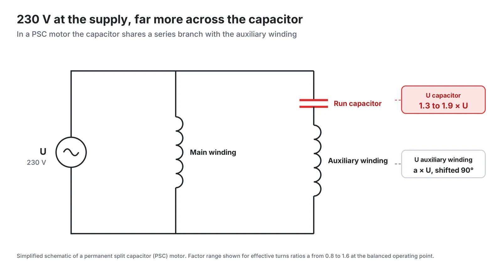
- A run capacitor shares a series branch with the auxiliary winding, so its voltage is set by the motor design, the load and the supply, not by the supply alone.
- Even with a turns ratio of 1, the capacitor sees 1.41 times the supply voltage.
- Only a measurement across the load range shows where the maximum capacitor voltage lies for a given motor.
Why the capacitor sees more than the mains
The capacitor is not connected across the supply. It sits in series with the auxiliary winding, and that series branch is connected to the supply alongside the main winding. The supply voltage is therefore shared between the auxiliary winding and the capacitor, and because the two voltages are far from in phase, they do not simply add up to the supply voltage.
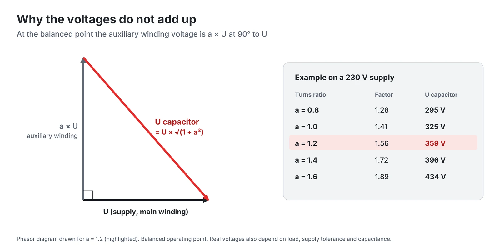
The purpose of the capacitor is to shift the auxiliary winding current ahead of the main winding current, so that the two windings produce a rotating field. At the balanced operating point the two currents are close to quadrature, and the auxiliary winding voltage is close to the supply voltage U multiplied by the effective turns ratio a between the auxiliary and main windings, and close to 90 degrees from U.
The capacitor voltage is the difference between the supply voltage and the auxiliary winding voltage. Two phasors at right angles subtract like the sides of a right triangle, which gives the relation for the balanced point:
Even with a turns ratio of 1, the capacitor sees 1.41 times the supply voltage. Published motors use turns ratios well away from 1, for example 0.7 in a capacitor-run compressor motor and 3.4 in a laboratory single-phase induction motor, so the factor varies from design to design.
How large the rise is
On a 230 V supply the balanced-point relation gives 295 V at a turns ratio of 0.8, 325 V at 1.0, 359 V at 1.2, 396 V at 1.4 and 434 V at 1.6. These are values at nominal supply and at the balanced operating point. Real operation moves away from both.
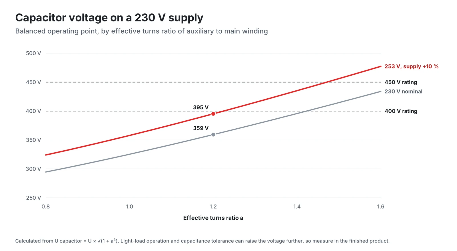
Four factors push the working voltage up or down in service:
- Supply voltage. In the balanced-point relation the capacitor voltage scales with the supply. If the supply is 10 % above nominal, 253 V, a motor that sees 359 V at 230 V sees about 395 V.
- Load. A fixed capacitor balances the motor at one operating point only, because the capacitance needed for balance is large at locked rotor and much smaller at full speed. Only a measurement across the load range shows where the maximum capacitor voltage lies for a given motor.
- Capacitance value. IEC 60252-1 lists the influence of capacitance as a separate subclause under the choice of rated voltage (9.2.2). A part at the upper end of its tolerance, or a replacement with a different value, moves the operating point away from the one the motor was designed for.
- Transients. Switching transients add stress on top of the RMS value, and IEC 60252-1 includes a check of transients in its guidance (9.4).
In the calculated example, a supply 10 % above nominal takes a motor with a turns ratio of 1.2 from 359 V to about 395 V, close to a 400 V rating.
What IEC 60252-1 says
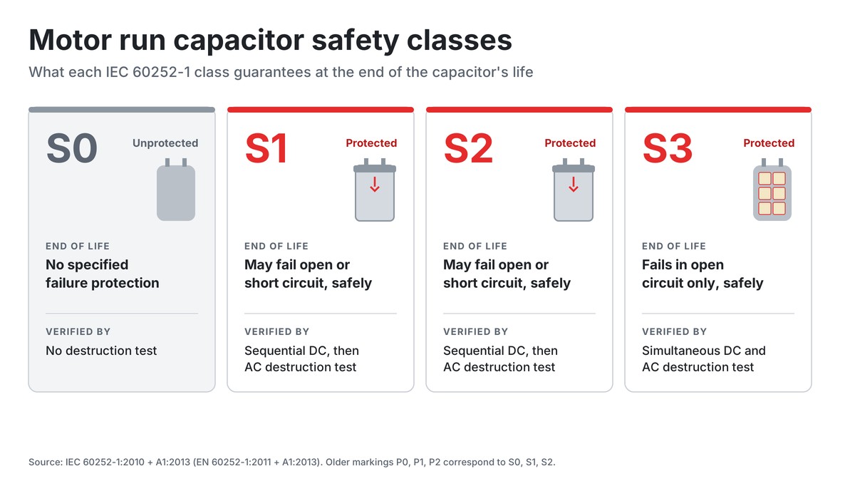
IEC 60252-1:2010 + A1:2013 states three objects: uniform rules for performance, testing and rating, specific safety rules, and guidance for installation and operation. Clause 9, Guidance for installation and operation, covers the third.
Subclause 9.2, Choice of rated voltage, is followed by 9.2.1, Measurements of working voltage, and 9.2.2, Influence of capacitance. The headings tie the choice of rated voltage to a measurement of the working voltage and to the capacitance. Subclause 9.3 adds a check of the capacitor temperature and 9.4 a check of transients.
Clause 6.1 on the maximum permissible voltage states that operation above the rated voltage will reduce the life expectancy of the capacitor. That wording was introduced in the 2010 edition. A rated voltage chosen too close to the working voltage therefore costs life.
Measuring the working voltage correctly
The goal is the highest RMS voltage the capacitor will see in service, plus the peak stress on top of it. A single reading at the bench supply and rated load misses most of that.
- Measure across the capacitor terminals in the finished equipment. IEC 60252-1 calls for measurements of the working voltage (9.2.1). Use an instrument rated for the voltage, for example a true-RMS meter with isolated inputs or an oscilloscope with a differential probe.
- Set the supply to its upper limit. Use a variable transformer and run at the highest supply voltage the equipment is specified for.
- Cover every operating state. Measure at no load, at rated load and at maximum load, at every speed tap, and for reversible motors such as shutter drives in both directions of rotation.
- Account for capacitance. Record the actual capacitance of the test part, or repeat the worst case with a part at the upper end of the tolerance band.
- Capture the waveform. Note the peak value and the shape, not only the RMS reading, to see transients (IEC 60252-1, 9.4).
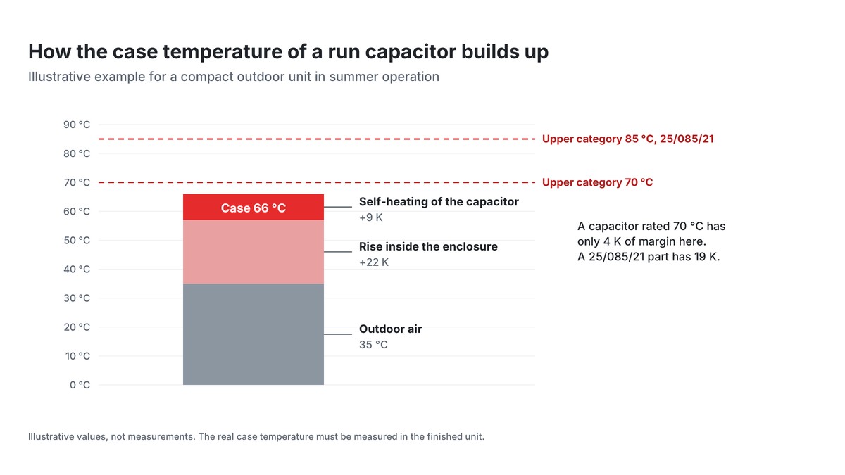
- Record the temperature at the same time. Measure the capacitor case temperature in the worst-case run (IEC 60252-1, 9.3), since the lifetime model commonly applied to film capacitors depends on both voltage and temperature.
A run capacitor can hold its charge after the supply is switched off. Discharge it through a suitable resistor before touching the terminals.
What over-voltage costs
In the simplified lifetime model commonly applied to film capacitors, life falls with a power of the ratio between the working voltage and the test voltage, so a capacitor running above its rating ages faster rather than failing at once. In a metallized polypropylene capacitor, breakdowns at local weak points, for example due to overvoltage, are cleared by self-healing, each with a small capacitance reduction, and as they accumulate the capacitance falls towards the end of life. The class of operation, A to D, is stated together with the rated voltage, and IEC 60252-1 states that operation above the rated voltage will reduce the life expectancy.
The effect then feeds back into the motor. The capacitance sets the balance between the windings, and a motor that moves away from balance has a double-frequency torque pulsation. A small capacitance also gives a small phase shift of the auxiliary current and a small starting torque.
For replacement parts the rule follows directly: a replacement keeps the capacitance and carries the same or a higher rated voltage, never a lower one. For new designs the aim is a rating with a margin over the measured worst case.
A worked example
The numbers below are illustrative and show the method, not a particular motor.
A fan motor for a 230 V product has an effective turns ratio of 1.2. At the balanced point and nominal supply the capacitor sees 230 V × 1.56 = 359 V. If the specified upper supply limit is 253 V, this becomes 395 V. Suppose the measurement then shows that at no load and 253 V the capacitor voltage rises further, to 410 V RMS. A 400 V capacitor would run above its rating whenever the supply is high and the fan lightly loaded. A 450 V capacitor keeps about 10 % margin over the measured worst case, and is the sound choice.
Checklist for choosing the rated voltage
- Start from the measured capacitor voltage, never from the supply voltage.
- Measure at the highest specified supply voltage, at every load, speed and direction.
- Include the capacitance tolerance and any planned replacement value.
- Check the peak value and waveform for transients.
- Check the capacitor temperature in the same worst-case run.
- Choose the next standard rating that leaves a margin over the worst case, and confirm it with the capacitor manufacturer when the margin is small.
- For service parts, keep the capacitance and use the same or a higher rated voltage.
Conclusion
A run capacitor shares a series branch with the auxiliary winding, so its voltage is set by the motor design, the load and the supply, not by the supply alone. At the balanced point it is the supply voltage multiplied by the square root of 1 + a², and the supply level, the load and the capacitance move it from there. Measure the worst case in the finished product and choose the rating with margin, so that the capacitor runs within the rated voltage on which its class of operation is based.
HYDRA motor run capacitors and documents
HYDRA motor run capacitors are made with rated voltages from 280 V AC to 500 V AC, depending on the series. The HYDRA catalogue 2025 gives a maximum allowable operating voltage of 1.1 × Un for both the S0 and the S2 types and states the class of operation together with the rated voltage, for example class A (30 000 h) at 420 V and class B (10 000 h) at 470 V for 1 to 100 µF.
| Series | Safety class | Rated voltage | Capacitance | Datasheet |
|---|---|---|---|---|
| 285 | S0 | 400 to 450 V AC | 0.8 to 30 µF | Series 285 (PDF) |
| 400 | S0 | 400 to 500 V AC | 0.8 to 40 µF | Series 400 (PDF) |
| 321 | S2 | 280 V AC | 1 to 100 µF | Series 321 (PDF) |
| 322 | S2 | 400 V AC | 2 to 20 µF | Series 322 (PDF) |
| 500 | S2 | 400 to 500 V AC | 1 to 80 µF | Series 500 (PDF) |
Further documents:
- HYDRA products, including motor run and start capacitors
- Stock types
- HYDRA capacitors catalogue 2025 (PDF), with life classes, approvals and general technical data
- Documents and certificates: VDE certificates, ISO 9001, RoHS and REACH
References
- IEC 60252-1:2010+AMD1:2013 CSV, AC motor capacitors, Part 1: General, Performance, testing and rating, Safety requirements, Guidance for installation and operation, consolidated edition 2.1. Abstract on the IEC Webstore (change in 6.1) and free IEC preview (Clause 1 object, table of contents with 6.1, 9.2 to 9.4).
- IEC 60038:2009+AMD1:2021 CSV, IEC standard voltages, edition 7.1. Free IEC preview (foreword: 230 V added to Table 1).
- T. A. Lettenmaier, D. W. Novotny, T. A. Lipo, Single-phase Induction Motor with an Electronically Controlled Capacitor, IEEE Transactions on Industry Applications 27(1), 1991, pp. 38 to 43. Free copy, University of Wisconsin MINDS repository (introduction, balanced operation, torque pulsation).
- T. J. E. Miller et al., Line-Start Permanent-Magnet Motor Single-Phase Steady-State Performance Analysis, IEEE Transactions on Industry Applications 40(2), 2004, pp. 516 to 525. Free copy, University of Glasgow ePrints (capacitor in series with the auxiliary winding, turns ratio 0.7).
- Michigan State University, Biosystems and Agricultural Engineering, Electrical Tech Note 313, Single-Phase Induction Motor Types (capacitor in the auxiliary winding, PSC motor, starting torque).
- H. Wang, F. Blaabjerg, Reliability of Capacitors for DC-Link Applications in Power Electronic Converters: An Overview, IEEE Transactions on Industry Applications 50(5), 2014. Free version of record, Aalborg University (section III, self-healing and lifetime model, equation 2).
- HYDRA capacitors catalogue 2025 (PDF), motor running capacitors.

Ask a HYDRA engineer
Send us your application data and our engineers will help you choose the right film capacitor. HYDRA has made film capacitors since 1899, with production in Jičín (Czech Republic) and Da Nang (Vietnam).
Ask an engineerCheck stock