Motor Run Capacitor Safety Classes S0 to S3: How to Specify Failure Protection under IEC 60252-1
In this article
A motor run capacitor datasheet states capacitance, tolerance, rated voltage, temperature range and life class. The safety class is a separate entry. It says nothing about how the capacitor performs in normal operation. It states the degree of safety protection the capacitor offers when it fails.
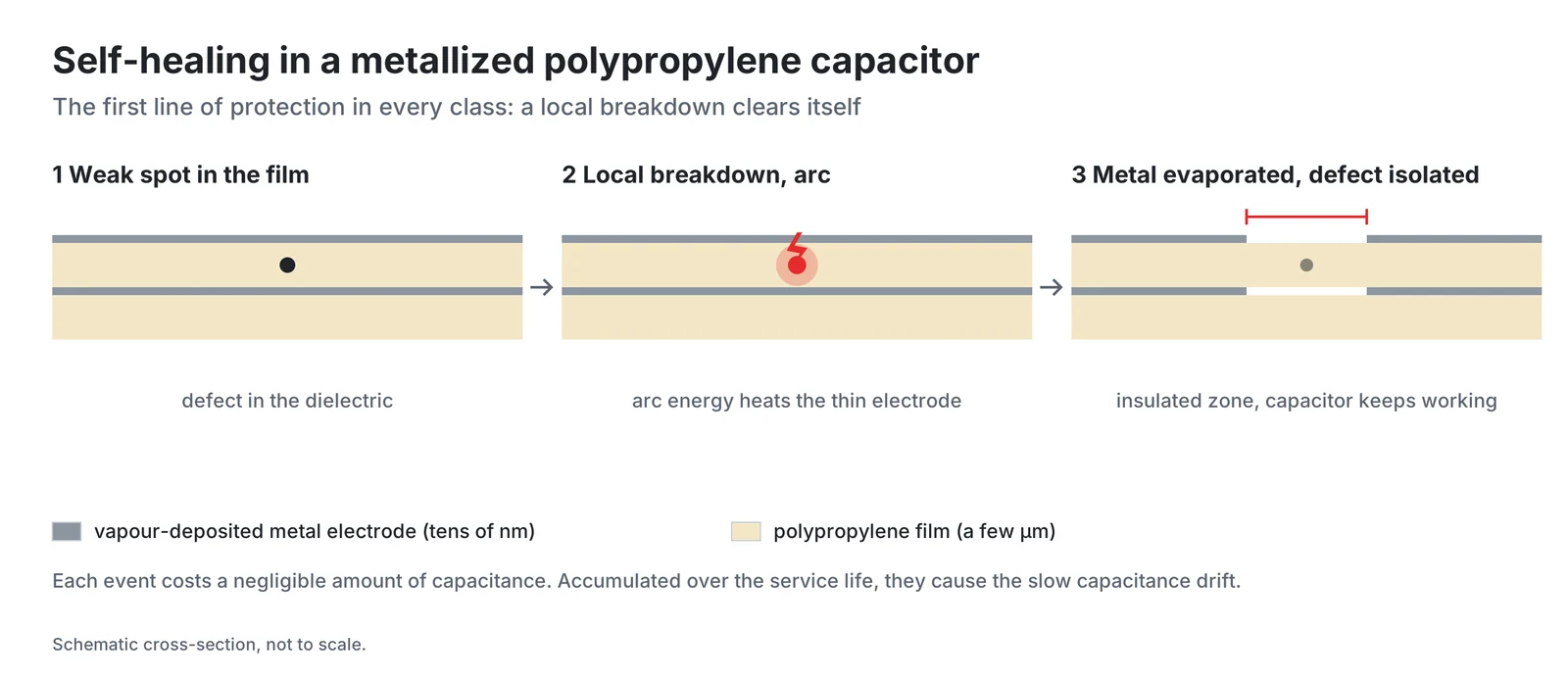
Metallized polypropylene (MKP) capacitors are self-healing. A local breakdown of the dielectric is cleared, and the capacitor keeps working with a negligible capacitance reduction. A capacitor can still fail. IEC 60252-1 distinguishes failure in the open-circuit and in the short-circuit mode, and in the worst case a failing metallized film capacitor can build up internal pressure and catch fire or explode. IEC 60252-1 identifies the degree of safety protection with one of four codes marked on the capacitor, S0, S1, S2 or S3. This article explains what each class means, how the protection works physically, and what to consider when choosing a class for an appliance, pump, compressor or fan.
Key takeaways
- IEC 60252-1 identifies the degree of safety protection with one of four codes marked on the capacitor, S0, S1, S2 or S3.
- S1 and S2 add an overpressure disconnect device verified by a sequential destruction test, and S2 is designed to fail in the open-circuit mode only.
- State the class together with the class of operation and the climatic category, and treat the datasheet's mounting and clearance instructions as part of the safety concept.
The standard behind the classes
The safety classes are defined in IEC 60252-1, AC motor capacitors, Part 1: General, Performance, testing and rating, Safety requirements, Guidance for installation and operation. The current edition is the second edition of 2010 with Amendment 1 of 2013, published as a consolidated version 2.1. In Europe it is adopted as EN 60252-1:2011 + A1:2013, and in Germany as DIN EN 60252-1 (VDE 0560-8):2014-07. CENELEC approved both the IEC 2010 text and its 2013 amendment as European Standards without any modification.
The scope is clearly bounded. The standard covers capacitors connected to the windings of asynchronous motors supplied from a single-phase system at frequencies up to 100 Hz, including capacitors that let three-phase motors run from a single-phase supply. Rated voltages go up to 660 V, and the dielectric may be paper, plastic film or a combination, metallized or with metal-foil electrodes. Motor start capacitors are covered by IEC 60252-2. Shunt capacitors for AC power systems up to 1 000 V (IEC 60831-1), capacitors for power electronic circuits (IEC 61071) and small AC capacitors for fluorescent and discharge lamps (IEC 61048) are explicitly excluded.
Older documents may carry the earlier markings P0, P1 and P2, which the standard lists as the former names of S0, S1 and S2. Class S3 has no former P name. It refers to segmented film construction, which the 2010 edition defined in 3.6, and Amendment 1 of 2013 gives segmented designs their own destruction test.
The four classes at a glance
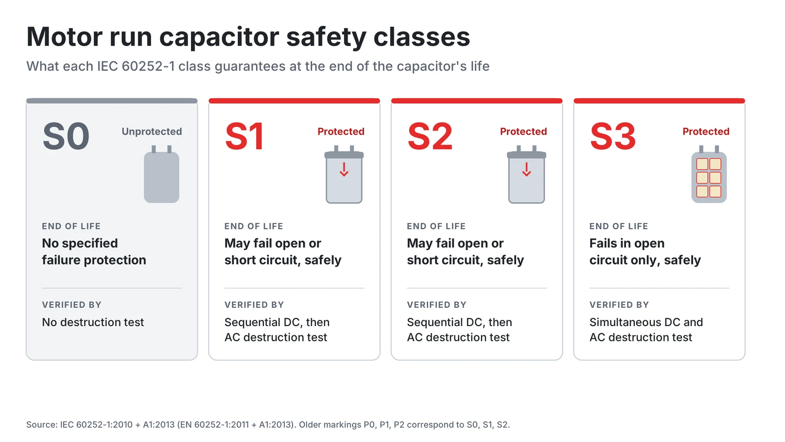
Definition 3.22 and subclause 5.16.1, both as amended in 2013, give each class its failure behaviour, its construction and its test.
| Class | Failure behaviour (definition 3.22) | Construction named in 5.16.1 | Destruction test in EN 60252-1:2011 + A1:2013 |
|---|---|---|---|
| S0 | No specific failure protection | Not specified | Not required |
| S1 | May fail in the open-circuit or short-circuit mode, protected against fire or shock hazard | Overpressure disconnect device | Sequential DC and AC test (5.16.3, 5.16.5) |
| S2 | Designed to fail in the open-circuit mode only, protected against fire or shock hazard | Overpressure disconnect device | Sequential DC and AC test (5.16.3, 5.16.5) |
| S3 | Fails with low residual capacitance, below 1 % of rated capacitance, protected against fire and shock hazard | Segmented film | Simultaneous DC and AC test (5.16.4, 5.16.6) |
S1 and S2 are verified by the same sequential test and differ in the permitted failure mode. An S1 capacitor may fail either as an open circuit or as a short circuit, while an S2 capacitor is designed to fail only as an open circuit. S0 means the capacitor type has no specific failure protection, so any protection against the consequences of its failure has to come from the equipment around it.
How the protection works
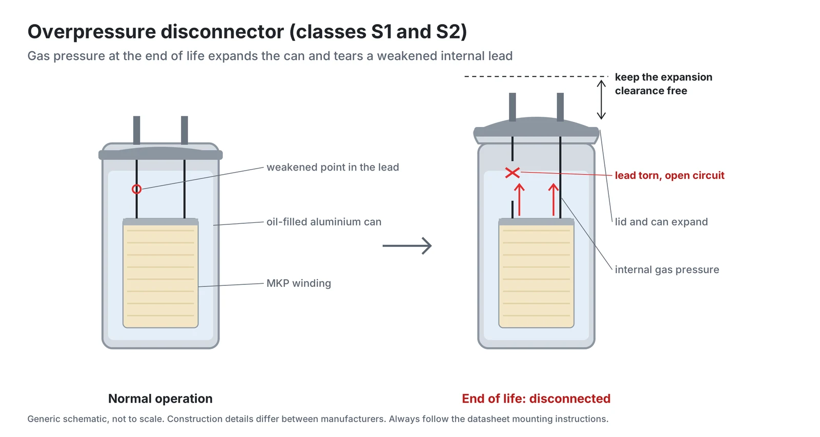
All three protected classes start from a self-healing dielectric and add a second mechanism, an overpressure disconnect device in S1 and S2 or segmented film in S3.
Self-healing, the first line in every class. In a metallized film capacitor the electrode is a metal layer typically less than 100 nm thick on the dielectric film. When the polymer breaks down at a weak spot, the current through the defect evaporates the metal layer around it until the defect is insulated. The capacitor regains its full ability except for a negligible capacitance reduction. As these isolated weak points accumulate, the capacitance falls gradually, and most metallized film capacitors fail because the capacitance drops below the required tolerance.
Overpressure disconnector (S1, S2). When a capacitor of this kind is destroyed, gas generation and a temperature increase raise the internal pressure. In HYDRA's S2 series the can then expands axially by up to about 9 mm, the thinner section of an internal fuse breaks, and the capacitor is disconnected from the mains. Two practical consequences follow. The expansion needs free space, so the datasheet specifies a minimum clearance of about 12 mm between the terminal and neighbouring components. And the mechanism works through pressure inside a closed can, and IEC 60252-1 includes a sealing test (5.12) among its tests.
Segmented film (S3). Here the protection is built into the metallization. The electrode is divided into metallic areas separated by non-metallic lines. The standard requires an S3 capacitor to fail with low residual capacitance, below 1 % of its rated capacitance, and to be protected against fire and shock hazard. UL 810 likewise distinguishes segmented film type protection from expansion type protection.
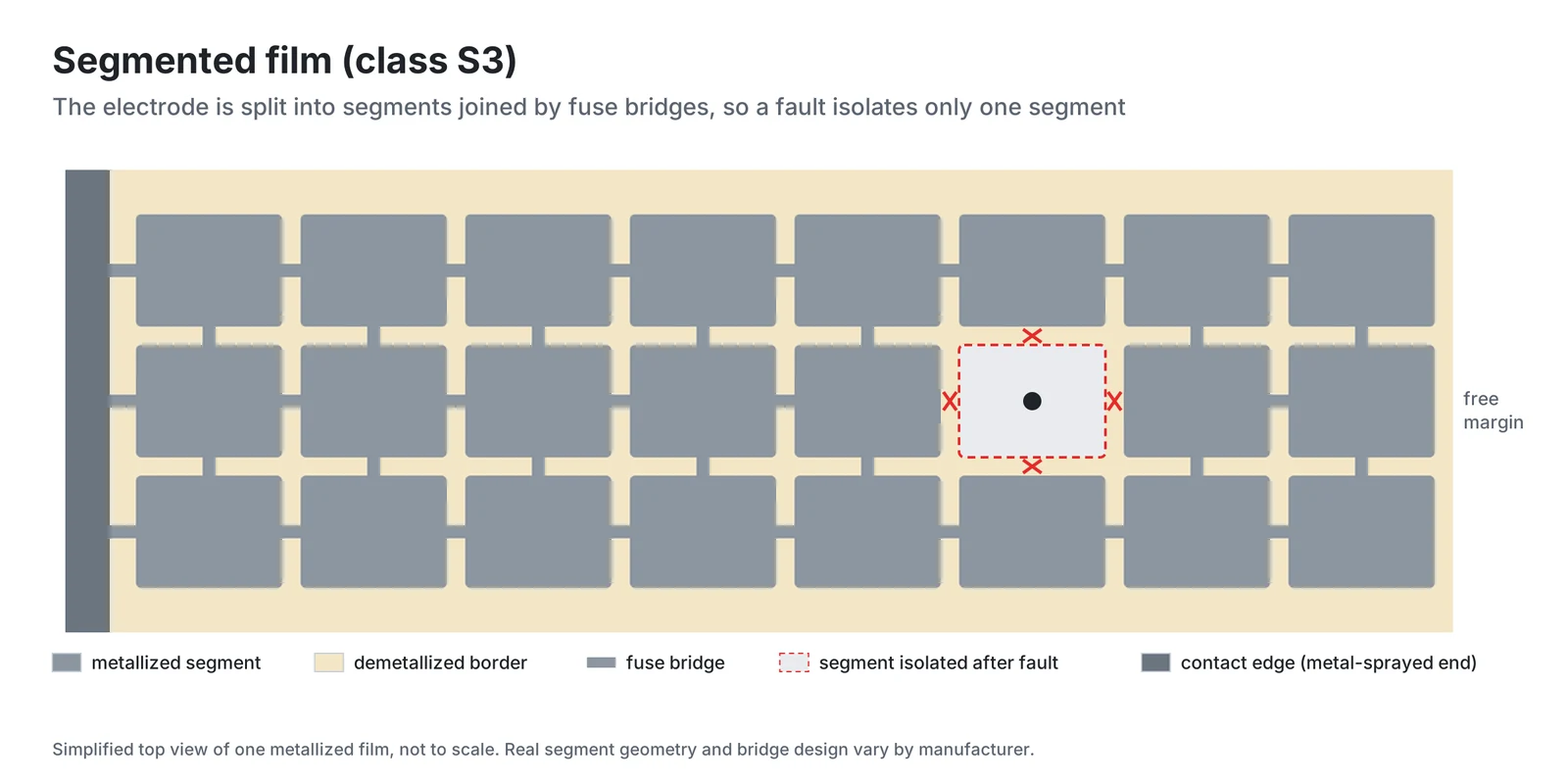
The two approaches protect with different physics, and the standard verifies them with different test procedures.
How the classes are verified
Classes S1, S2 and S3 are verified in the destruction test of clause 5.16. The standard calls this test optional, and capacitors marked S0 are not required to be tested.
For S1 and S2 the test is sequential. The specimens are first conditioned with DC and then subjected to an AC destruction test in a circuit that includes a variable inductor (Figures 2 to 4 of the standard). For S3 the DC and AC stresses are applied simultaneously. In both cases clause 5.16.7 sets how the failure is evaluated.
Besides the destruction test, IEC 60252-1 contains endurance (5.13), damp heat (5.14) and self-healing (5.15) tests and tests of resistance to heat, fire and tracking (5.17: ball pressure, glow wire and tracking). Table 1 of the standard gives the type test schedule.
Safety class is not class of operation
The safety class says how the capacitor fails. The class of operation, defined in 3.9 of the standard, says how long it is expected to last. The two are separate entries and both belong in a specification.
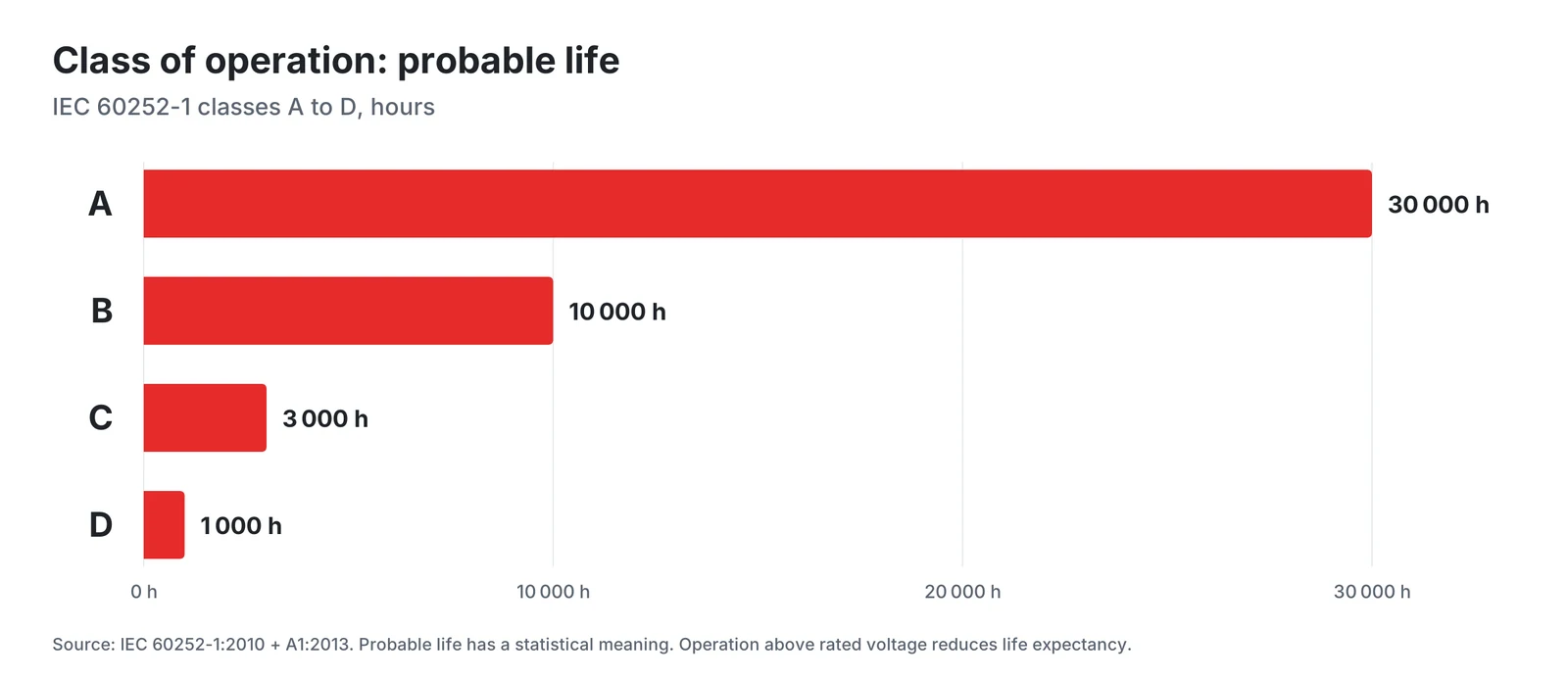
Since the 2010 edition the class of operation includes the concept of probable life, with reference to statistics. Clause 6.1 adds that operation above the rated voltage will reduce the life expectancy of the capacitor. A datasheet therefore combines several independent statements. HYDRA series 321, for example, is specified for 280 V, 50/60 Hz, life class B (10 000 h), safety class P2 (S2) and climatic category 25/85/21 according to IEC 60068, which gives the minimum temperature, the maximum temperature and the damp heat severity, here -25 °C and +85 °C.
Choosing S0, S2 or S3 in practice
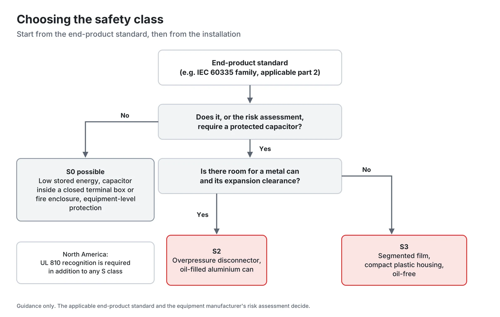
IEC 60252-1 makes the destruction test optional, so the capacitor standard itself does not require any particular class. Start with the end product and its installation, not with the capacitor catalogue.
The end-product standard comes first. Household and similar appliances with a rated voltage up to 250 V single-phase or 480 V otherwise fall under IEC 60335-1. It has a normative Annex F on capacitors and lists IEC 60252-1:2010 among its normative references, so check the capacitor requirements of the applicable parts before fixing the class. For North America, UL 810 Part I covers enclosed capacitors with integral protection intended to reduce the risk of rupture and venting of the enclosure under internal fault conditions, for use with appliances, air conditioning and refrigeration equipment, motors and the like. It is a separate standard from IEC 60252-1.
S0 leaves protection against the consequences of a capacitor failure to the equipment, because the capacitor type has no specific failure protection.
S2 is the class to specify when the capacitor itself must be designed to fail in the open-circuit mode only, with protection against fire or shock hazard. It needs room for the can to expand. HYDRA's S2 datasheets specify a clearance of about 12 mm from the terminal to neighbouring components.
S3 provides protection through segmented film construction instead of an overpressure disconnect device, and requires the capacitor to fail with a residual capacitance below 1 % of its rated capacitance.
Specification checklist for a motor run capacitor
- Capacitance and tolerance, checked against the motor manufacturer's recommendation.
- Rated voltage, chosen from the working voltage measured at the capacitor (IEC 60252-1, 9.2).
- Frequency, 50 Hz, 60 Hz or both.
- Class of operation (A to D) for the required life.
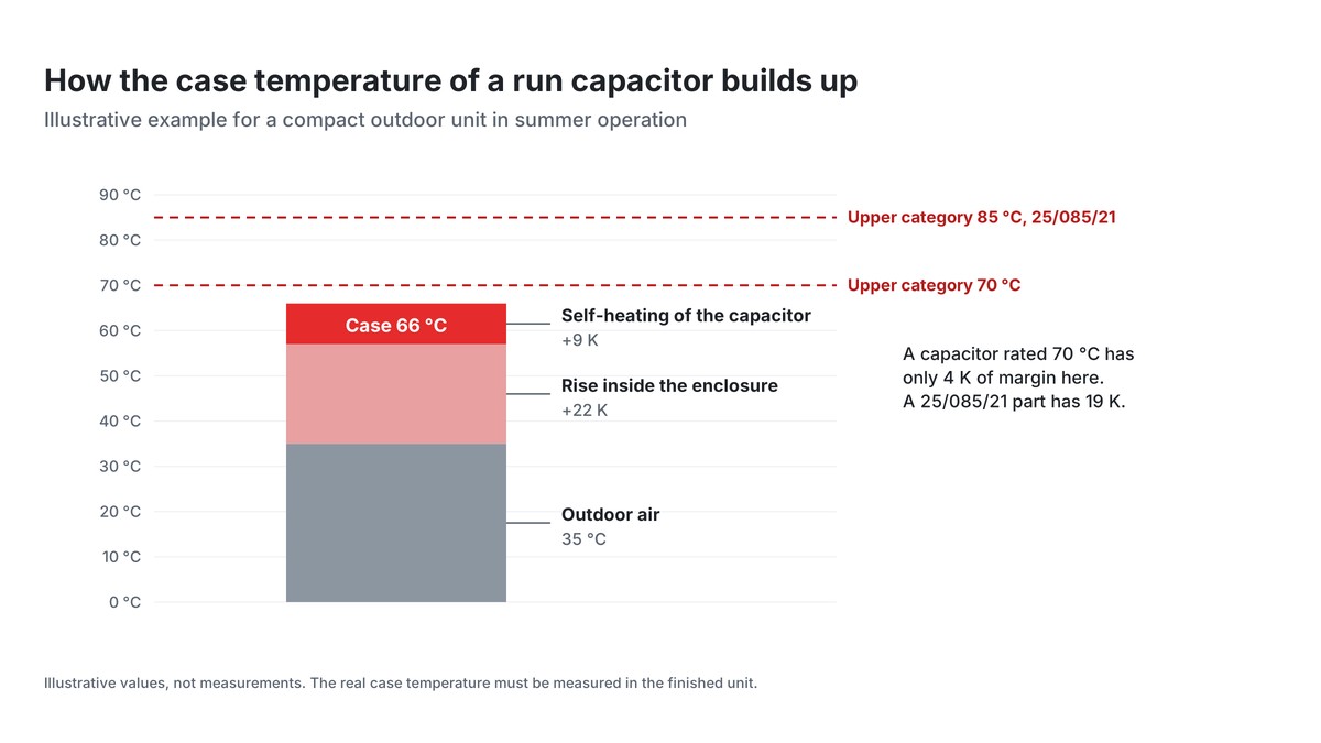
- Climatic category, checked against the capacitor temperature in the equipment (IEC 60252-1, 9.3).
- Safety class S0, S1, S2 or S3, chosen for the end product.
- Approvals the market needs, for example a VDE certificate to EN 60252-1 for Europe and UL 810 recognition for North America, and the production site they cover.
- Mechanics: case, terminals, mounting stud, cable length, and for S1 or S2 parts the expansion clearance and mounting position stated in the datasheet.
Conclusion
The safety class is a one-character field. S0 has no specific failure protection. S1 and S2 add an overpressure disconnect device verified by a sequential destruction test, and S2 is designed to fail in the open-circuit mode only. S3 relies on segmented film and must fail with a residual capacitance below 1 % of rated capacitance. State the class together with the class of operation and the climatic category, and treat the datasheet's mounting and clearance instructions as part of the safety concept.
HYDRA motor run capacitors and documents
HYDRA motor run capacitors are made in two of the classes discussed above: S0 in a dry, resin-potted design and S2 with an overpressure disconnector. The datasheets state the mounting conditions that belong to the safety concept. For series 321, for example, the can may extend axially by up to about 9 mm when the disconnector operates, and a clearance of about 12 mm to neighbouring components is required.
| Series | Safety class | Rated voltage | Capacitance | Datasheet |
|---|---|---|---|---|
| 285 | S0 | 400 to 450 V AC | 0.8 to 30 µF | Series 285 (PDF) |
| 400 | S0 | 400 to 500 V AC | 0.8 to 40 µF | Series 400 (PDF) |
| 321 | S2 | 280 V AC | 1 to 100 µF | Series 321 (PDF) |
| 322 | S2 | 400 V AC | 2 to 20 µF | Series 322 (PDF) |
| 500 | S2 | 400 to 500 V AC | 1 to 80 µF | Series 500 (PDF) |
Further documents:
- HYDRA products, including the series 330 motor start capacitor, and capacitors available from stock
- HYDRA capacitors catalogue 2025 (PDF), with approvals and general technical data
- Documents and certificates: VDE certificates, UL files E129223 and E201956, CQC, UKCA, ISO 9001, RoHS and REACH
References
- IEC 60252-1:2010+AMD1:2013 CSV, AC motor capacitors, Part 1: General, Performance, testing and rating, Safety requirements, Guidance for installation and operation, consolidated edition 2.1. Abstract on the IEC Webstore (scope, changes in 3.6, 3.9 and 6.1) and free IEC preview (Clause 1 with the exclusions, table of contents with 5.12 to 5.17 and 9.2 to 9.3, definition 3.5).
- EN 60252-1:2011/A1:2013 (IEC 60252-1:2010/A1:2013), definition 3.22 classes of safety protection S0 to S3 and subclause 5.16.1. Free sample SIST EN 60252-1:2011/A1:2014, iTeh Standards.
- EN 60252-1:2011, endorsement notice. Free sample SIST EN 60252-1:2011, iTeh Standards.
- DIN EN 60252-1 (VDE 0560-8):2014-07, German version EN 60252-1:2011 + A1:2013. VDE VERLAG.
- IEC 60252-2:2010+AMD1:2013 CSV, AC motor capacitors, Part 2: Motor start capacitors.
- IEC 60335-1:2020, Household and similar electrical appliances, Safety, Part 1: General requirements, edition 6.0. Free IEC preview (Clause 1 Scope, Clause 2 with IEC 60252-1:2010, Annex F Capacitors in the table of contents).
- UL 810, Capacitors, 6th edition (2019, revised 2025), scope 1.1. UL Standards & Engagement.
- R. Gallay, Metallized Film Capacitor Lifetime Evaluation and Failure Mode Analysis, CERN Yellow Reports CERN-2015-003, p. 45. doi:10.5170/CERN-2015-003.45, sections 1 and 2.
- H. Wang, F. Blaabjerg, Reliability of Capacitors for DC-Link Applications in Power Electronic Converters: An Overview, IEEE Transactions on Industry Applications 50(5), 2014. Free version of record, Aalborg University, section III.A.
- HYDRA datasheets series 321 (overpressure disconnector, 9 mm expansion, 12 mm clearance) and series 285 (life classes A to D, climatic category notation).

Ask a HYDRA engineer
Send us your application data and our engineers will help you choose the right film capacitor. HYDRA has made film capacitors since 1899, with production in Jičín (Czech Republic) and Da Nang (Vietnam).
Ask an engineerCheck stock