Motor Start Capacitors: Duty Cycle, Switching Count and Film Versus Electrolytic
In this article
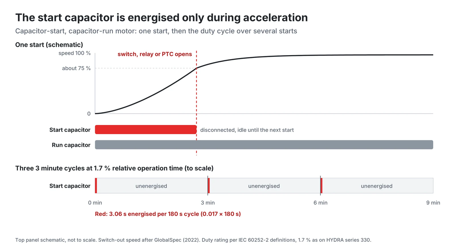
A start capacitor is energised for only a short time. IEC 60252-2 describes starting operation as a special type of intermittent operation in which the capacitor is energized for only a very short period while the motor is accelerating to rated speed [2]. Then it is switched out and sits idle until the next start, so it is rated very differently from a run capacitor.
This article explains how IEC 60252-2 expresses that duty, why the switching device matters, and how film start capacitors compare with AC electrolytic types.
Key takeaways
- A start capacitor is rated for a duty, not for continuous operation.
- The short duty depends on the switching device, and the capacitor rating is only valid while the device disconnects the capacitor on time.
- Metallized film start capacitors are the alternative covered by the same standard.
What the start capacitor does
IEC 60252-2 defines a motor starting capacitor as a power capacitor which provides a leading current to an auxiliary winding of a motor and which is switched out of circuit once the motor is running [2]. A running capacitor, in contrast, is usually connected permanently to the motor winding and remains in circuit throughout the running period. During the starting period, if it is in parallel with the starting capacitor, it helps to start the motor [2].
The start winding is not built to carry that current continuously. A guide for HVAC technicians states that single-phase compressor start windings are not designed to carry high continuous current, and that a start capacitor left in circuit too long keeps the start winding current high and risks damaging the winding [8]. The same guide describes potential relays sized to open when the motor reaches about 80 % of its full speed [8].
How the standard expresses intermittent duty
IEC 60252-2 covers start capacitors for asynchronous motors supplied from a single-phase system at the frequency of the mains: metallized capacitors with a paper or plastic film dielectric as well as electrolytic capacitors with non-solid electrolyte, with rated voltages up to and including 660 V [1]. Run capacitors are covered by IEC 60252-1 [4].
IEC 60252-2 defines intermittent operation as operation in which periods with the capacitor energized are followed by intervals during which the capacitor is unenergized, and starting operation as a special type of it [2]. The rated duty itself appears on the datasheet: HYDRA series 330, for example, is marked 330 V AC (AB 1.7 % ED) [5].
The examples below read the percentage as the share of each duty cycle in which the capacitor is energised. This reading is an assumption of the examples. The exact definition and the rated cycle duration should be taken from IEC 60252-2 or confirmed with the capacitor manufacturer.
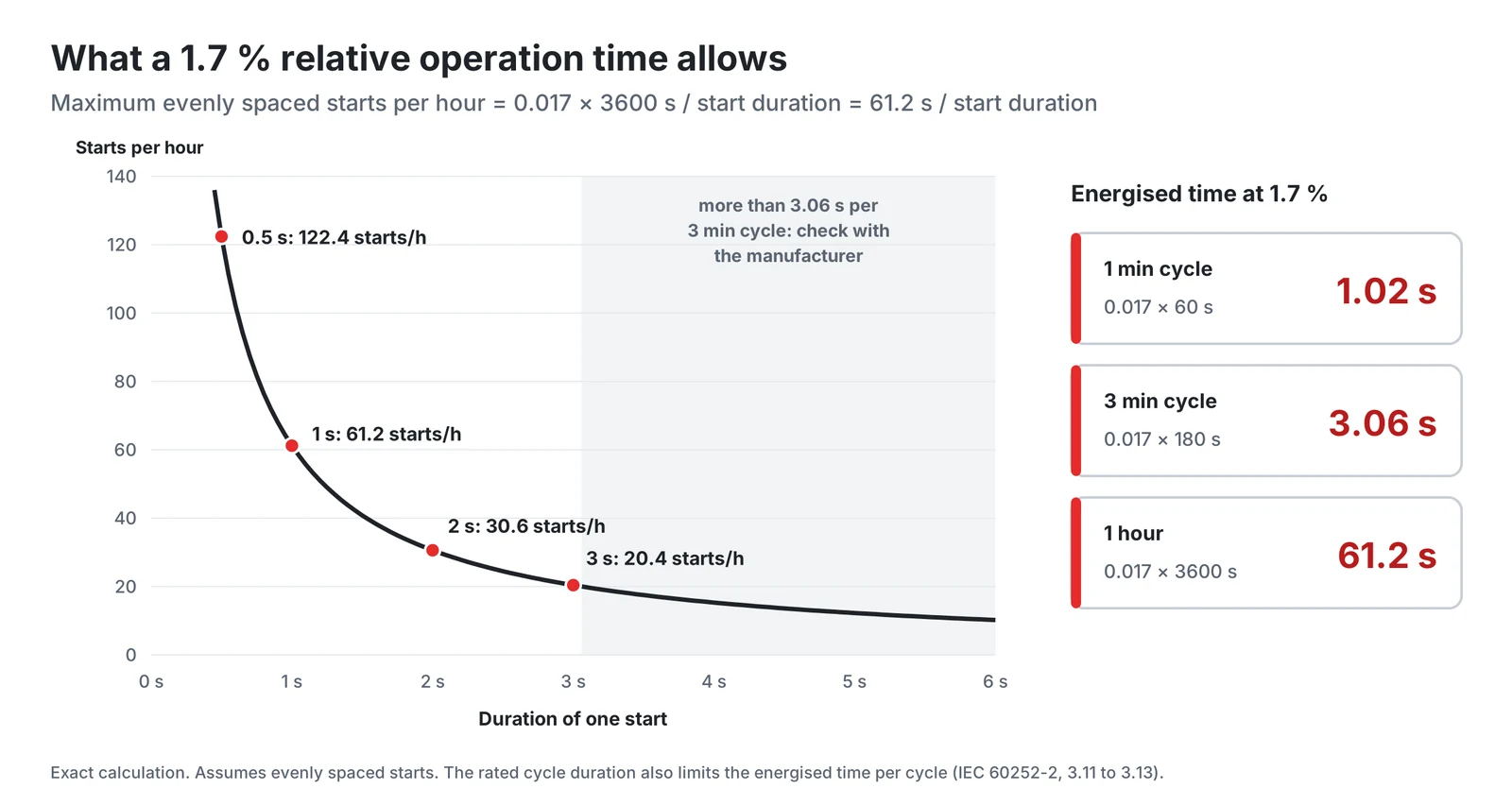
Under that reading, the cycle duration matters as much as the percentage: a percentage alone would allow one 61 s start per hour, a very different stress from twenty starts of three seconds. The energised time per cycle is:
For a 1.7 % rating this gives 0.017 × 60 s = 1.02 s in a 1 minute cycle, 3.06 s in a 3 minute cycle and 61.2 s in one hour. With evenly spaced starts, the maximum number of starts per hour is 61.2 s divided by the duration of one start: about 61 starts of 1 s, 30 of 2 s or 20 of 3 s.
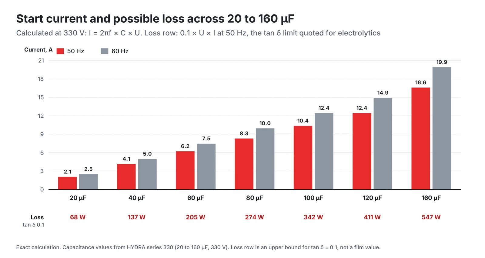
Frequency matters too. The capacitive reactance is 1/(2πfC) [9], so at the same voltage the capacitor current is proportional to frequency and is 20 % higher at 60 Hz than at 50 Hz. Whether a 50 Hz duty rating has to be reduced for 60 Hz operation should be taken from the datasheet of the chosen capacitor or confirmed with its manufacturer.
Why the switching device matters
The short duty depends on the switching device, and the capacitor rating is only valid while the device disconnects the capacitor on time. Various types of relays and controls can remove a start capacitor from the circuit [8]. Three are discussed here:
- Centrifugal switch: opens at a speed set by the motor design. Take the switch-out speed from the motor manufacturer.
- Potential relay: for compressors the most common device according to [8], sized to open when the motor reaches about 80 % of its full speed. It responds to the back EMF, which increases as the motor spins faster [8].
- PTC thermistor: heats up under the starting current. A trade article on PTC start devices states that in less than half a second its resistance increases enough to practically stop the current, and that a time delay lets it cool down to its initial temperature before the next restart [7].
The rising voltage concerns the capacitor as well. The back EMF measured at the capacitor increases as the motor spins faster [8], and IEC 60252-2 sets a maximum permissible voltage for each technology (5.2.1 and 6.2.1) [1]. HYDRA series 330 allows a maximum operating voltage of 1.1 times the rated voltage [5]. A late switch-off therefore means both longer energised time and higher voltage.
Where start and run capacitors are fitted together, check the discharge devices. IEC 60252-2 defines a discharge device as one capable of reducing the voltage between the terminals effectively to zero, within a given time, after the capacitor has been disconnected [2], and contains requirements on discharge devices for both technologies (5.3.4 and 6.3.4) [1].
Electrolytic or film
According to a guide for HVAC technicians, most start capacitors have a much higher microfarad rating than run capacitors and are generally electrolytic [8]. Metallized film start capacitors are the alternative covered by the same standard. IEC 60252-2 treats the two technologies in separate clauses: self-healing start capacitors with a destruction test, and electrolytic start capacitors with a pressure relief test and storage guidance [1].
| Property | AC electrolytic | MKP film, HYDRA series 330 |
|---|---|---|
| Dielectric | Oxide layer, non-solid electrolyte | Metallized polypropylene, self-healing |
| Capacitance tolerance | See datasheet | ±5 % |
| Loss factor | See datasheet | Low (stated qualitatively) |
| Life statement | See datasheet | 500 000 switching operations |
| End of life protection | Pressure relief, tested to IEC 60252-2 | Overpressure disconnector, class S2 |
| Temperature range | See datasheet | -25 °C to +60 °C |
The loss factor sets the heat generated in each start. With the capacitive reactance 1/(2πfC) [9], a 100 µF capacitor at 330 V and 50 Hz carries:
That is about 3.4 kvar. The dissipation factor is tan δ = ωRsC [10], so the loss in the series resistance equals tan δ times the reactive power. With an assumed loss factor of tan δ = 0.1, an illustrative value, the loss would be about 340 W during the start, or roughly 1 kJ in a 3 s start. The HYDRA series 330 datasheet specifies a low dissipation factor [5], which reduces the heat generated in each start.
HYDRA series 330 is an example of the film approach: MKP-Si technology in an aluminium can filled with vegetable oil, rated 330 V AC with the marking AB 1.7 % ED, 50 or 60 Hz, 20 to 160 µF, climate category 25/60/21, a life class of 500,000 switching operations and safety class S2 (formerly P2) with an overpressure disconnector [3][5]. The maximum permissible operating voltage is 1.1 times the rated voltage and the maximum current 1.3 times the rated current. Because the can may expand by up to about 9 mm when the disconnector operates, the datasheet asks for about 12 mm of clearance between the terminal and neighbouring components [5]. The HYDRA catalogue lists the motor capacitor range as compliant with EN 60252-1 and EN 60252-2 [6].
What do 500,000 switching operations mean in service? At 20 starts per hour, the maximum for 3 s starts at 1.7 % under the reading above, they correspond to 25,000 operating hours and to about 417 hours of energised time. A machine that starts six times per hour, an illustrative figure, would reach the count after about 83,000 operating hours, or 9.5 years of continuous running.
Checklist for selecting a start capacitor
- Measure the start time under worst-case conditions: low mains voltage, cold start, full load.
- Count starts per hour, including restarts, and keep the energised time per cycle within the rated duty of the datasheet.
- Check the voltage at the capacitor terminals up to the moment of disconnection.
- Reduce the rated duty for 60 Hz if the manufacturer requires it.
- Consider what happens if the switching device fails, and whether end-of-life protection is needed.
- In capacitor-start, capacitor-run motors, check the discharge device requirements.
- Compare the capacitor's life statement with the starts expected over the product life.
Conclusion
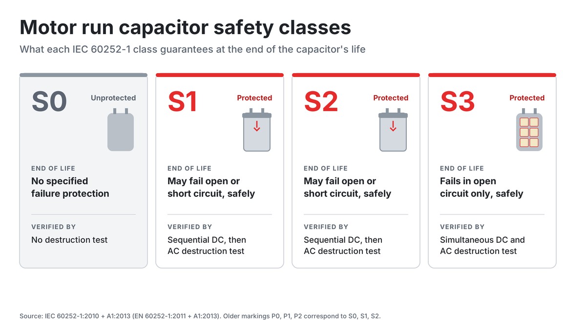
A start capacitor is rated for a duty, not for continuous operation. Read as the energised share of each cycle, the familiar 1.7 % means about 61 seconds of energised time per hour, and the cycle duration decides how that time may be split into starts. The rating holds only while the centrifugal switch, relay or PTC disconnects the capacitor on time. Electrolytic types are the most common start capacitors, while film start capacitors such as HYDRA series 330 offer a low dissipation factor, ±5 % tolerance, a stated switching count and S2 protection. An earlier article in this series covers the safety classes S0 to S3 in detail.
This article gives general design guidance. The final selection should always be confirmed with the capacitor manufacturer's datasheets and application engineers for the specific series and operating conditions.
HYDRA motor start capacitors and documents
HYDRA series 330 is a metallized polypropylene start capacitor in MKP-Si technology, filled with vegetable oil and protected by an overpressure disconnector. Its datasheet states the ratings below. HYDRA also makes motor run capacitors in safety classes S0 and S2 for capacitor-start, capacitor-run motors.
| Parameter | Series 330 |
|---|---|
| Rated voltage | 330 V AC (AB 1.7 % ED) |
| Rated frequency | 50 Hz / 60 Hz |
| Capacitance | 20 to 160 µF, ±5 % |
| Life class | 500 000 switching operations |
| Climatic category | 25/60/21 |
| Max. operating voltage and current | 1.1 × UN, 1.3 × IN |
Further documents:
- Series 330 start capacitor datasheet (PDF)
- HYDRA capacitors catalogue 2025 (PDF), with the motor run capacitor ranges and general technical data
- HYDRA product overview
- Documents and certificates: VDE, UL, UKCA, ISO 9001, RoHS and REACH
- Contact HYDRA for application support
References
- IEC 60252-2:2010+AMD1:2013 CSV, AC motor capacitors, Part 2: Motor start capacitors, edition 2.1. Free IEC preview with Clause 1 Scope and the table of contents (5.1.16, 5.2.1, 5.3.4, 6.1.14, 6.2.1, 6.3.4, 7.5).
- EN 60252-2:2011 (IEC 60252-2:2010), definitions 3.1, 3.2, 3.7, 3.9 and 3.10. Free sample of SIST EN 60252-2:2011.
- EN 60252-2:2011/A1:2013 (IEC 60252-2:2010/AMD1:2013), definition 3.29 and subclause 5.1.16.1. Free sample of SIST EN 60252-2:2011/A1:2014.
- IEC 60252-1:2010+AMD1:2013 CSV, AC motor capacitors, Part 1, edition 2.1. Free IEC preview, Clause 1 Scope.
- HYDRA a.s., Hydra Start Capacitors for AC Motors, MKP-Si technology series 330, datasheet (PDF).
- HYDRA a.s., Hydra Capacitors catalogue 2025 (PDF).
- J. Tomczyk, Meet the Positive Temperature Coefficient Resistor, ACHR News, 2002.
- B. Orr, Start Capacitor and Inrush Facts and Myths, Part 3, HVAC School, 19 November 2018.
- OpenStax, University Physics Volume 2, 15.2 Simple AC Circuits, equation 15.3 (capacitive reactance).
- H. Wang, F. Blaabjerg, Reliability of Capacitors for DC-Link Applications in Power Electronic Converters, An Overview, IEEE Trans. Industry Applications 50(5), 2014. Free version of record (Aalborg University), section II (tan δ = ωRsC) and Table I (oxide layer).

Ask a HYDRA engineer
Send us your application data and our engineers will help you choose the right film capacitor. HYDRA has made film capacitors since 1899, with production in Jičín (Czech Republic) and Da Nang (Vietnam).
Ask an engineerCheck stock