Wear-Out Versus Self-Healing: Why Film and Electrolytic Capacitors Age Differently
In this article
- How an aluminium electrolytic capacitor wears out
- End of life is a parametric limit, not a failure event
- When the electrolyte itself is wrong: leaking motherboard capacitors
- How a metallized film capacitor heals itself
- End of life for film: a few percent of capacitance
- What "life" means on each datasheet
- Comparing lifetime claims fairly
- Monitoring ageing in the field
- Conclusion
- HYDRA DC-link capacitors and documents
- References
Two capacitors can carry similar "life" figures and still age in completely different ways. An aluminium electrolytic capacitor wears out: its electrolyte evaporates, its ESR rises and its capacitance falls until a parameter crosses a defined limit. A metallized polypropylene film capacitor has no liquid electrolyte to lose. It ages through self-healing events at local weak points, each of which costs a negligible amount of capacitance, so its capacitance falls gradually, and capacitance is the parameter used to track its ageing.
This article explains both mechanisms, what the life figure on each datasheet means, how to compare lifetime claims fairly and how to watch the ageing in the field. An earlier article in this series covered when film can replace electrolytics in the DC link.
Key takeaways
- An aluminium electrolytic capacitor wears out: its electrolyte evaporates, its ESR rises and its capacitance falls until a parameter crosses a defined limit.
- The film capacitor heals local breakdowns and loses capacitance slowly, with end of life defined by a few percent of capacitance change.
- Compare life claims only at the same temperature, stress and end-of-life definition, and use condition monitoring to see where each part actually stands.
How an aluminium electrolytic capacitor wears out
An aluminium electrolytic capacitor contains a liquid electrolyte, and the electrolyte is the part that ages. A review of DC-link capacitor reliability names electrolyte vaporization as the major wear-out mechanism of small electrolytics such as snap-in types, because of their relatively high ESR and limited heat dissipation surface, and describes the resulting wear-out as a drift of capacitance, ESR, tan δ and leakage current [1].
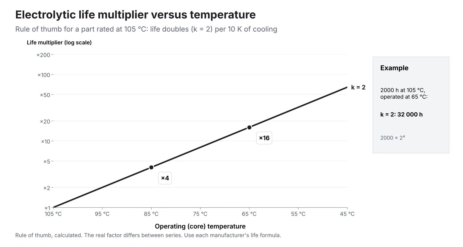
Ambient temperature is a critical stressor of electrolyte vaporization [1]. The familiar rule of thumb is that life doubles for every 10 K reduction in temperature. The same review presents this rule as a simplified form of the Arrhenius lifetime model popularly applied to electrolytic and film capacitors and notes that this temperature dependence is an approximation only [1]. Ripple current adds internal heating: the power dissipated in the capacitor is the ESR multiplied by the square of the RMS ripple current [5], and the review lists ripple current among the critical stressors of electrolyte vaporization [1].
Here L₀ is the rated life at the rated temperature T₀ and T is the actual operating temperature. For a part rated 2000 h at 105 °C operated at 65 °C, the rule gives 2000 × 2⁴ = 32 000 h. Different capacitor manufacturers use different variants of the lifetime model [1], so the rule is a first estimate. The manufacturer's own life formula always takes precedence.
End of life is a parametric limit, not a failure event
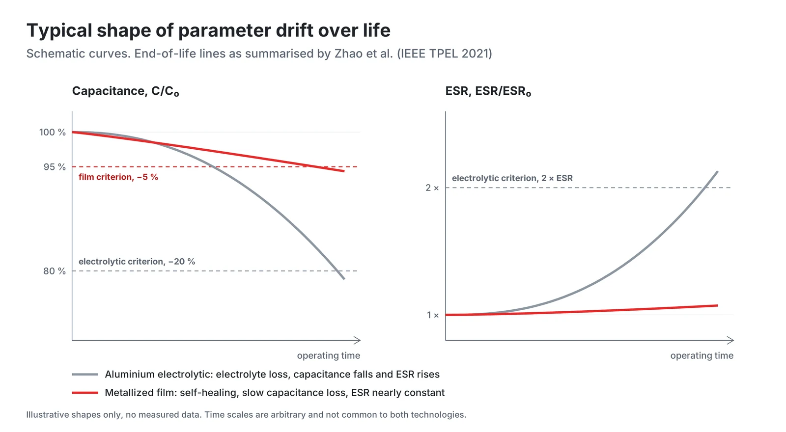
For an electrolytic, "end of life" usually means a parameter has drifted past a limit, not that the part has stopped working. Both DC-link reviews cited here give the typical end-of-life criteria for electrolytics as capacitance reduced by 20 % or ESR increased to twice the initial value [1], [5].
Wear-out is not the only way an electrolytic can fail. The same review lists open circuit and short circuit as further failure modes of electrolytics, besides wear-out by drift of the electrical parameters [1].
When the electrolyte itself is wrong: leaking motherboard capacitors
The importance of the electrolyte became painfully visible in the early 2000s. IEEE Spectrum reported in February 2003 that low-ESR aluminium electrolytic capacitors in desktop PCs had been breaking open and failing, with the first complaints about leaking capacitors at the end of 2001. According to sources quoted in the article, a scientist had taken an electrolyte formula from his employer in Japan, and the formula was later sold to an electrolyte maker in Taiwan, but "it didn't have the right additives." Capacitors made with it generated hydrogen gas, burst and leaked electrolyte onto the circuit board [2].
The lesson is not that electrolytics are unreliable, but that their life depends on the chemistry of the electrolyte.
How a metallized film capacitor heals itself
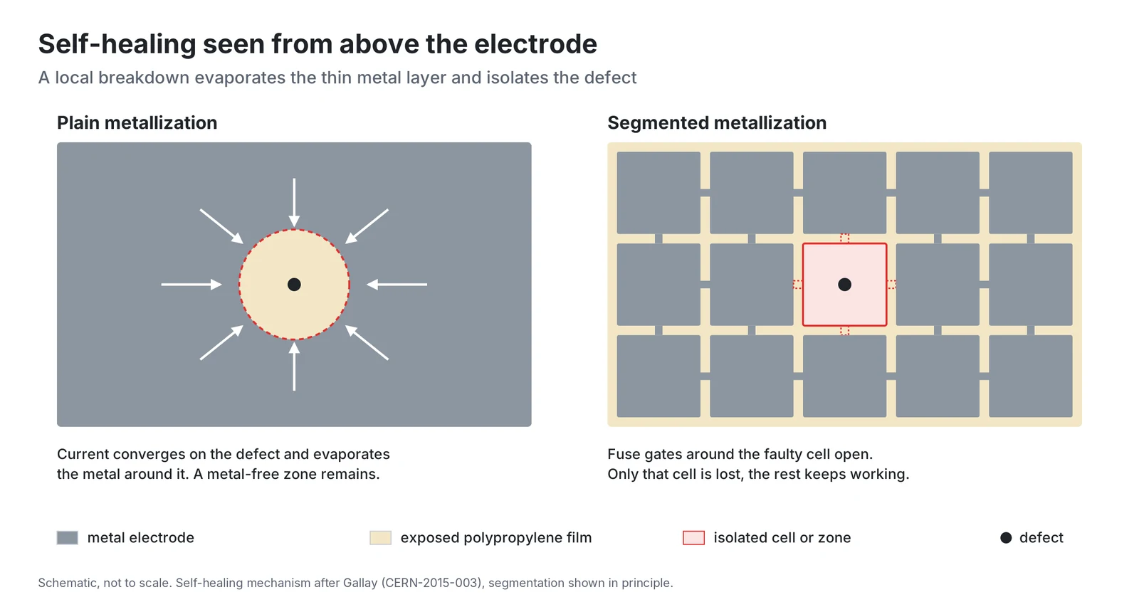
A metallized polypropylene capacitor uses a thin polypropylene film as the dielectric and an evaporated metal layer, of the order of 100 nm thick, as the electrode [1], [4]. When the dielectric breaks down at a weak point, the current increases through the defect and on the electrode near it. Close to the defect the current density becomes high enough to evaporate the metal layer. In a well-designed capacitor the process stops when the metal-free zone is large enough to insulate the defect and small enough not to damage the film [4].
A thicker metal layer has lower resistance, but higher energies are then involved in the self-healing process, leading to greater damage [4]. In segmented metallization, the active electrode is divided into metallic areas separated by non-metallic lines [4]. Amendment 1 of IEC 60252-1 defines class S3 for motor capacitors of segmented film construction, which are required to fail with low residual capacitance, below 1 % of the rated value, and have protection against fire and shock hazard [3].
End of life for film: a few percent of capacitance
Each clearing event costs very little capacitance, but over years at voltage, temperature and humidity, together with slow corrosion of the metallization, the losses add up [4]. Gallay notes that most metallized film capacitors fail because the capacitance drops below the required tolerance [4]. Both DC-link reviews give a capacitance reduction of 5 %, that is capacitance below 95 % of the initial value, as the typical end-of-life criterion for film [1], [5].
A film capacitor that reaches its criterion still works, only with less capacitance. Wang and Blaabjerg describe how initial breakdowns at local weak points are cleared, the capacitor regains its full ability except for a negligible capacitance reduction, and the capacitance falls gradually as such isolated points accumulate [1]. Film capacitors are not immune to every failure: Gallay describes how design or production faults or excessive stress can produce a conductive channel through the winding, with leakage current, heating and a rise of internal pressure [4].
What "life" means on each datasheet
Life figures are ratings under stated conditions. The motherboard capacitors in the IEEE Spectrum report, for example, were rated for 4000 hours of continuous ripple current [2]. For metallized film, Gallay relates the expected lifetime to a capacitance-drop tolerance and shows how a failure rate in FIT at a given temperature and voltage translates into hours: 50 FIT at 40 °C and half the rated voltage corresponds to a lifetime expectancy of 2.1 × 10⁶ h for a 10 % capacitance-drop tolerance [4]. Motor run capacitors use the classes of operation of IEC 60252-1, which the 2010 edition clarified with the concept of probable life [7], discussed in an earlier article in this series. The HYDRA DC-link datasheet states a life expectancy of 100 000 h at rated voltage and below 70 °C hot spot for the EGB DCL and EBB DCL series [6].
Comparing lifetime claims fairly
Before comparing two life figures, check that they share:
- The same temperature reference. A life figure refers to a stated temperature, such as the hot spot in the HYDRA DC-link datasheet [6]. Translate both figures to the real core or hot-spot temperature.
- The same stress. Voltage and ripple current matter. In the common life model the voltage exponent typically varies from 3 to 5 for electrolytics, while values from about 7 to 9.4 are used by capacitor manufacturers for metallized polypropylene film, as summarised by Wang and Blaabjerg, so film life responds much more strongly to voltage [1].
- The same end-of-life definition. A -20 % capacitance and 2 × ESR limit is not a -5 % limit.
- The same failure fraction. Do the hours describe a parametric limit, a share of failed parts or a FIT rate at reduced stress?
- The same extrapolation basis. Use each manufacturer's own formula for the final calculation.
Monitoring ageing in the field
Because both technologies age through measurable parameters, a drive can watch them. Zhao et al. group the methods into three principles: estimating capacitance and ESR from the periodic ripple already present in the converter, using non-periodic charge or discharge profiles such as the DC link discharge at shutdown, and data-driven models trained on operating data. For adjustable speed drives they recommend signal injection, the discharge profile and data training from the perspective of estimation accuracy and hardware cost [5]. Wang and Blaabjerg list capacitance, ESR or both as the degradation precursors of electrolytics and capacitance as the precursor for film capacitors [1]. For a film DC link, a slow capacitance trend toward the end-of-life criterion is therefore the parameter to watch.
Conclusion
The electrolytic wears out as its electrolyte evaporates, its ESR rises and its capacitance falls, with life roughly doubling per 10 K of cooling in the simplified model and end of life defined by wide parametric limits. The film capacitor heals local breakdowns and loses capacitance slowly, with end of life defined by a few percent of capacitance change. Compare life claims only at the same temperature, stress and end-of-life definition, and use condition monitoring to see where each part actually stands.
This article gives general design guidance. The final selection should always be confirmed with the capacitor manufacturer's datasheets and application engineers for the specific series and operating conditions.
HYDRA DC-link capacitors and documents
HYDRA DC-link capacitors are metallized polypropylene film capacitors of the kind described above, with a dry polyurethane/epoxy resin filling instead of a liquid electrolyte. The datasheet states a life expectancy of 100 000 h at rated voltage and a hot spot below 70 °C, a capacitance tolerance of ±10 % and conformity with IEC 61071, with UL file E201956.
| Series | Terminals | Rated voltage | Capacitance | Series resistance | Datasheet |
|---|---|---|---|---|---|
| EGB DCL | M6 internal thread | 700 to 1500 V DC | 120 to 2800 µF | 0.8 to 4.1 mΩ | DC-link datasheet (PDF) |
| EBB DCL | M8 bolt | 700 to 1500 V DC | 120 to 2800 µF | 0.8 to 4.1 mΩ | DC-link datasheet (PDF) |
Further documents:
- HYDRA products, including DC-link, AC filter, power factor correction and motor capacitors
- Stock types
- HYDRA capacitors catalogue 2025 (PDF), with general technical data
- Documents and certificates: ISO 9001, RoHS and REACH
References
- H. Wang, F. Blaabjerg, Reliability of Capacitors for DC-Link Applications in Power Electronic Converters: An Overview, IEEE Transactions on Industry Applications 50(5), pp. 3569 to 3578, 2014, DOI 10.1109/TIA.2014.2308357, free version of record at Aalborg University, Tables I to III and equation 2.
- S. K. Moore, Y.-T. Chiu, Leaking Capacitors Muck Up Motherboards, IEEE Spectrum, 1 February 2003.
- IEC 60252-1:2010/AMD1:2013, AC motor capacitors, Part 1, definition 3.22.4 (S3), free sample of SIST EN 60252-1:2011/A1:2014.
- R. Gallay, Metallized Film Capacitor Lifetime Evaluation and Failure Mode Analysis, CERN Yellow Report CERN-2015-003, Proceedings of the CAS-CERN Accelerator School: Power Converters, p. 45, open access (CC BY 4.0), also arXiv:1607.01540.
- Z. Zhao, P. Davari, W. Lu, H. Wang, F. Blaabjerg, An Overview of Condition Monitoring Techniques for Capacitors in DC-Link Applications, IEEE Transactions on Power Electronics 36(4), pp. 3692 to 3716, 2021, DOI 10.1109/TPEL.2020.3023469, accepted manuscript at Aalborg University, Table I and Sections IV and V.
- HYDRA a.s., DC Link Capacitors EGB DCL and EBB DCL, datasheet (PDF).
- IEC 60252-1:2010+AMD1:2013 CSV, AC motor capacitors, Part 1, IEC webstore abstract, list of significant technical changes.
Products in this article
Reliability & materials
Check stockAsk a HYDRA engineer
Send us your application data and our engineers will help you choose the right film capacitor. HYDRA has made film capacitors since 1899, with production in Jičín (Czech Republic) and Da Nang (Vietnam).
Ask an engineerCheck stock