Inside a PFC Capacitor Bank: Filling, Inrush Current, Contactors and Discharge
In this article
- What sits in each step
- Oil or nitrogen: what each filling trades
- The temperature category on the label
- The overpressure disconnector
- Inrush current in back-to-back switching
- Why capacitor contactors have damping resistors
- Discharge before reconnection
- Fuses and cables
- Conclusion
- HYDRA PFC capacitors and documents
- References
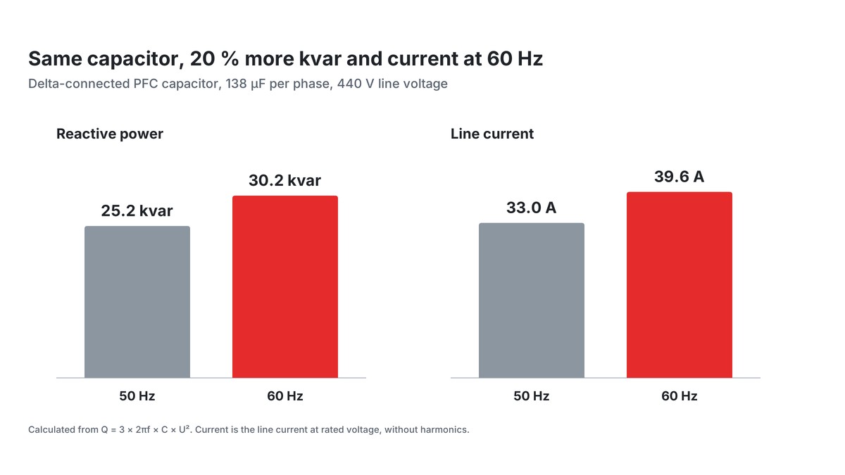
An automatic power factor correction bank looks simple on the single-line diagram: a controller, a few contactors and a row of cylindrical capacitors. Yet the details around each step decide how long the bank lasts: which capacitor filling suits the cabinet, what current flows when a step is switched onto an energised bank, how fast the capacitor must discharge before it is switched again, and how fuses and cooling are chosen. This article covers those details for low voltage banks of three-phase metallized polypropylene capacitors. Sizing of kvar at 50 and 60 Hz and the detuning of banks against harmonic resonance were covered in an earlier article in this series and are not repeated here.
Key takeaways
- The reliability of a PFC bank is decided in each step.
- The filling sets the thermal and mounting envelope, the overpressure disconnector separates a faulty capacitor safely, and inrush and discharge behaviour decide the stress on contactors and capacitors.
- A short calculation of the back-to-back peak and of the discharge time with the actual layout and components belongs in every design.
What sits in each step
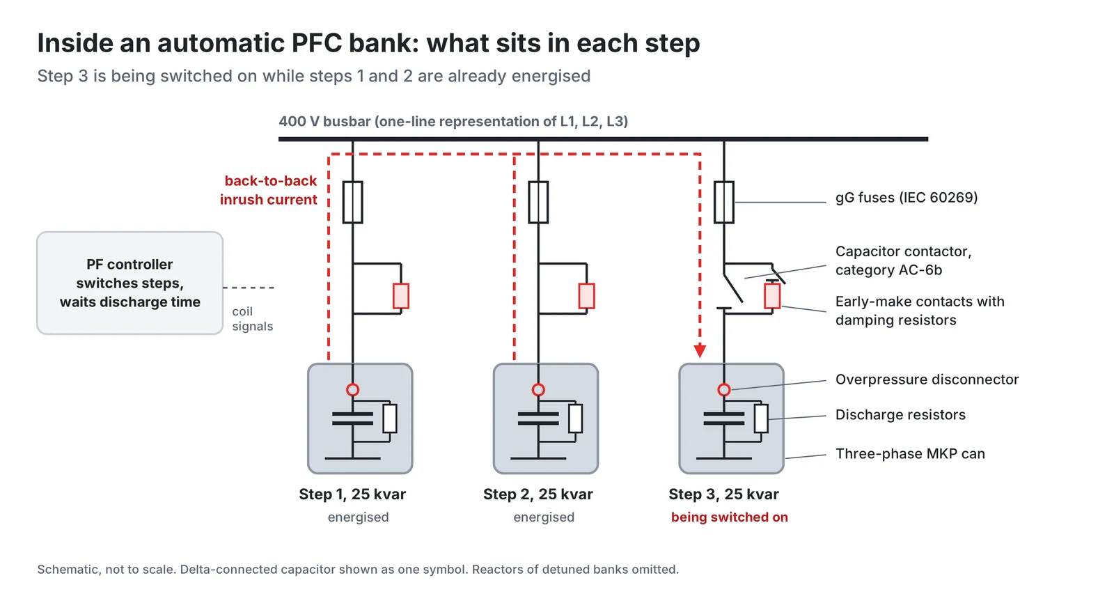
Every step of an automatic bank contains the same chain of parts. Short-circuit protection comes first, typically gG fuse-links to IEC 60269. Then follows a capacitor switching contactor, which HYDRA specifies according to IEC 60947-4-1. The capacitor itself is a three-phase unit with overpressure disconnectors on its active leads. IEC 60831-1 also requires a discharge device for each capacitor (Clause 22). The power factor controller switches the steps.
Oil or nitrogen: what each filling trades
HYDRA builds its PRB three-phase capacitors in two versions. PRB DPM is filled with oil or soft resin, PRB DPMg with nitrogen gas. Both use self-healing metallized polypropylene film and share the main electrical ratings: rated voltages from 230 to 690 V, overcurrent of 1.5 × In including harmonics, inrush current up to 200 × In, dielectric losses of 0.2 W/kvar and total losses below 0.4 W/kvar.
The differences are thermal and mechanical:
| Property | PRB DPM (oil or soft resin) | PRB DPMg (N₂ gas) |
|---|---|---|
| Lowest ambient | -25 °C | -45 °C |
| Maximum ambient | 60 °C | 55 °C |
| Mean over 24 h / 1 year | 50 °C / 40 °C | 45 °C / 35 °C |
| Mounting position | Vertical or horizontal | Any position |
| Rated power | 5 to 56 kvar | 5 to 35 kvar |
| Life expectancy | > 150 000 h | > 135 000 h |
The oil version accepts a 5 K higher ambient and larger kvar per can. The gas version mounts in any position and is rated down to -45 °C. The HYDRA 2025 catalogue quotes the life expectancy at 5000 switching operations per year.
The temperature category on the label
IEC 60831-1 marks the upper limit of the permissible ambient temperature range with letter symbols, defined in Table 1 of the standard. The HYDRA 2025 catalogue states the limits of each PRB version directly, as in the table above: the maximum ambient, the highest 24-hour mean and the highest annual mean.
The catalogue specifies the PRB capacitors for indoor application with natural or forced air cooling.
The overpressure disconnector
The HYDRA 2025 catalogue specifies overpressure expansion fuses on the active leads of the three-phase units. They disconnect the capacitor safely in case of abnormal operation, self-overheating or frequent overvoltage stress.
Inrush current in back-to-back switching
When a capacitor is switched onto an AC voltage, the result is a damped resonant circuit, and the capacitor takes a transient current in addition to its rated current. According to the HYDRA documentation for capacitor switching contactors, this transient current can reach a multiple of the rated current, as much as 200 times. In back-to-back switching, the new step is charged from the energised steps, and only the small inductance between them limits the current.
The back-to-back inrush of two capacitors is the response of a series LC circuit: the peak equals the initial voltage across the switch divided by the surge impedance √(L/Ceq), and the ringing frequency is 1/(2π√(L Ceq)), with Ceq = C1C2/(C1 + C2), as shown in the Michigan Technological University lecture listed in the references. For n identical steps, with n - 1 already energised and the same connection inductance Ln in every step, this gives for the peak:
with Î in amperes, Qn the step power in kvar, Ln the connection inductance of one step per phase in µH, and k1 = 1457 at 50 Hz (1330 at 60 Hz). The constant is √(2/3 × 10⁹ / 2πf), so the expression is the LC result written in practical units. The ringing frequency is f0 = 89.2 × U × √(1 / (Ln × Qn)) at 50 Hz, with U the line voltage in volts.
Worked example. A 400 V, 50 Hz bank has six steps of 25 kvar. With five steps energised, the sixth is switched on. Each step has In = 25 000 / (√3 × 400) = 36.1 A. Assume, as an input of this example, a connection inductance of 1 µH per step and phase. Then Î = 1457 × 5/6 × √(25 / 1) ≈ 6070 A, which is 168 times the rated current, at f0 = 89.2 × 400 × √(1/25) ≈ 7.1 kHz. With 0.5 µH the peak would rise to about 238 × In.
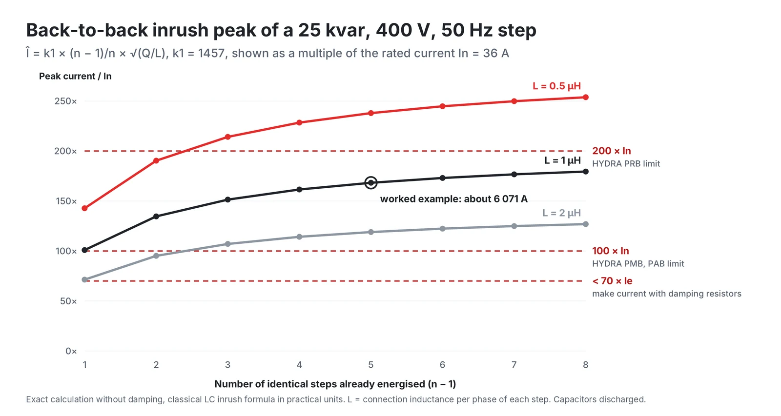
HYDRA PRB capacitors are specified for up to 200 × In, the smaller PMB and PAB ranges for 100 × In. The example sits inside the PRB limit, but a lower connection inductance could exceed it. The contactor is the other weak point: according to the HYDRA contactor documentation, such current spikes would lead to welding of the contactor's main contacts.
Why capacitor contactors have damping resistors
Capacitor contactors solve this with early-make contacts. The leading contacts close before the main contacts, and the inrush current spikes are limited or damped by resistance wires. HYDRA's K3 capacitor contactors limit the making current to below 70 × Ie in this way and are protected against contact welding for a prospective making current of 200 × Ie.
Discharge before reconnection
IEC 60831-1 contains a dedicated clause on the discharge device (Clause 22) and a discharge test (Clause 16). The required residual voltage and discharge time are set in the standard and in the datasheets of the capacitor and switchgear actually used. The example below assumes a target of 75 V within 3 minutes.
For a delta-connected 25 kvar, 400 V, 50 Hz capacitor, each phase has C = 25 000 / (3 × 2π × 50 × 400²) = 166 µF. The worst-case trapped voltage is the peak value √2 × 400 = 566 V. With a resistor R across each phase the voltage falls exponentially with the time constant τ = RC, so reaching 75 V within 180 s requires R ≤ 180 / (166 µF × ln(566/75)) ≈ 537 kΩ. A 470 kΩ resistor gives 75 V after about 157 s and dissipates about 1 W for the three phases at 400 V.
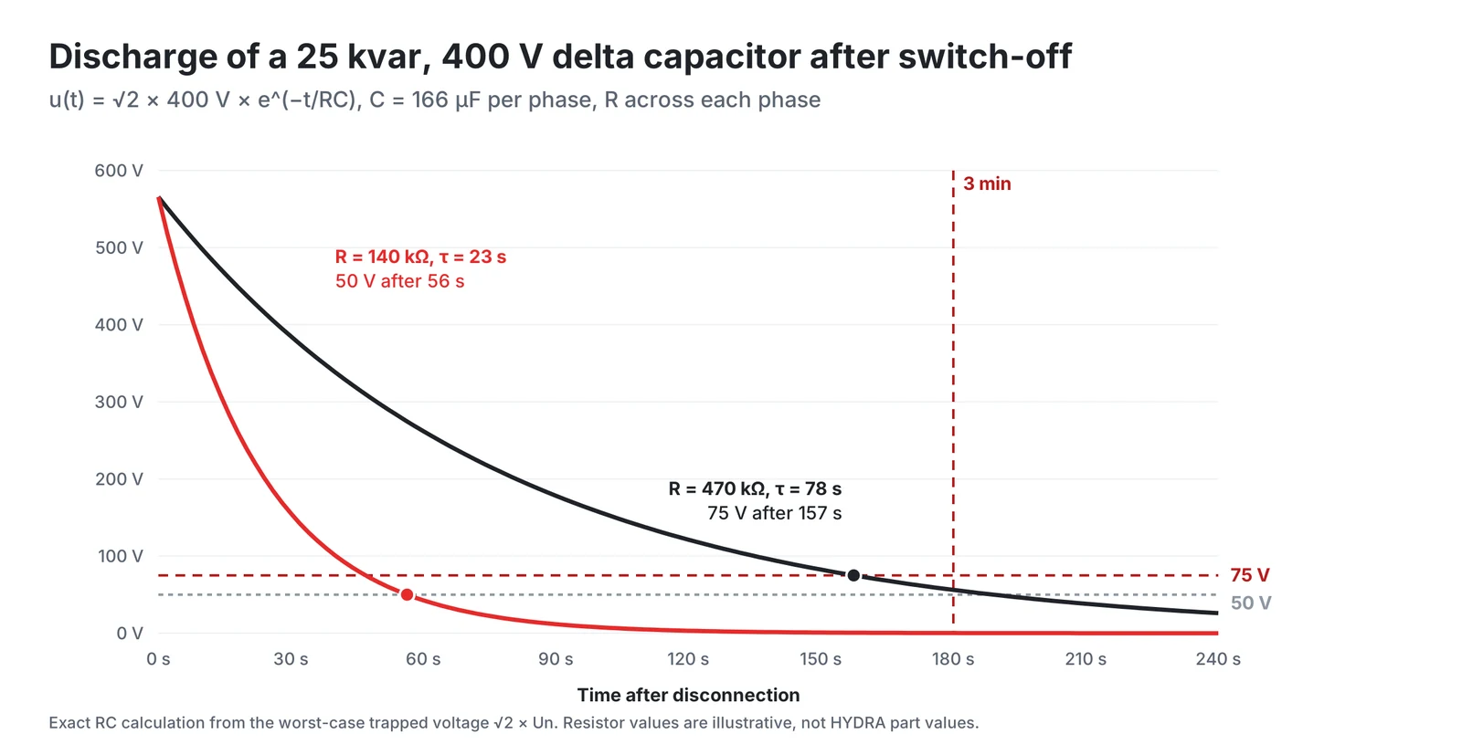
The discharge requirement is a safety requirement, not a switching rule. In the LC formula above, the peak current is proportional to the voltage across the switch at closing, so a capacitor still charged in the opposite polarity to the supply can see up to about twice the voltage difference. If the datasheets of the parts actually used specify a lower residual voltage before re-energising, that value applies. If 50 V is required in the example, 140 kΩ reaches 50 V in about 56 s at about 3.4 W, or external discharge devices are added. The discharge or reconnection time set in the power factor controller must be at least the time the actual capacitor needs to reach the permitted residual voltage.
Fuses and cables
HYDRA supplies PHN fuse-links of utilization category gG to IEC 60269 for the steps. Its K3 contactor table lists the matching gL (gG) fuse range for each contactor size, for example 35 to 63 A for the K3-18K and 50 to 80 A for the K3-24K. The fuse and cable selection should follow the current datasheets of the capacitor and switchgear used.
Conclusion
The reliability of a PFC bank is decided in each step. The filling sets the thermal and mounting envelope, the overpressure disconnector separates a faulty capacitor safely, and inrush and discharge behaviour decide the stress on contactors and capacitors. A short calculation of the back-to-back peak and of the discharge time with the actual layout and components belongs in every design. The final selection should always be confirmed against the current datasheets of the capacitor and switchgear used.
HYDRA PFC capacitors and documents
HYDRA makes three-phase PRB capacitors in an oil-filled (PRB DPM) and a nitrogen-filled (PRB DPMg) version, and the smaller PAB and PMB ranges. The same supply programme covers the other parts of a step discussed above: filter reactors, power factor controllers, gG fuse-links and K3 capacitor switching contactors with early-make contacts and damping resistors.
| Series | Connection | Rated voltage | Rated power | Inrush current | Operating temperature |
|---|---|---|---|---|---|
| PAB DPM(d) | 1-phase | 230 to 525 V AC | 1 to 6.5 kvar | max. 100 × In | -25 to +55 °C |
| PMB DPM(d) | 1 to 3-phase, delta | 230 to 525 V AC | 1 to 6.5 kvar | max. 100 × In | -25 to +55 °C |
| PRB DPMg | 1 to 3-phase, star or delta | 230 to 690 V AC | 5 to 35 kvar | max. 200 × In | -45 to +55 °C |
| PRB DPM(d) | 1 to 3-phase, star or delta | 230 to 690 V AC | 5 to 56 kvar | max. 200 × In | -25 to +60 °C |
Values from the HYDRA capacitors catalogue 2025.
Further documents:
- HYDRA capacitors catalogue 2025 (PDF) with the full PFC specification
- Components for power quality (PDF): filter reactors, PFC controllers, fuses and K3 capacitor switching contactors
- HYDRA product overview and stock types
- Certificates and declarations: UL file E129223, ISO 9001, RoHS and REACH
- Contact for the current datasheet of a specific capacitor
References
- HYDRA a.s., Hydra Capacitors 2025, product catalogue, PFC capacitors.
- HYDRA a.s., Components for Power Quality: filter reactors, PFC controllers, fuses, capacitor switching contactors (ed. 02/13), sections on fuse-links and capacitor switching contactors.
- IEC 60831-1:2014, Shunt power capacitors of the self-healing type for a.c. systems having a rated voltage up to and including 1 000 V, Part 1: General, Performance, testing and rating, Safety requirements, Guide for installation and operation, table of contents (Clause 16, Clause 22, Table 1). Free IEC preview (PDF).
- IEC 60947-4-1:2023, Low-voltage switchgear and controlgear, Part 4-1: Contactors and motor-starters, Electromechanical contactors and motor-starters.
- IEC 60269-1:2024, Low-voltage fuses, Part 1: General requirements.
- B. Mork, Learning the Basic Concepts of Capacitor Bank Switching (PDF), EE 5220 lecture slides, Michigan Technological University, energization inrush and back-to-back energization.
- OpenStax, University Physics Volume 2, 10.5 RC Circuits, Discharging a Capacitor, equation 10.11.
- C. Nelson, Chapter 8.4-5, Complex Power and Power Factor (PDF), ENGR 228 Circuit Analysis lecture slides, Walla Walla University, slide 12 (QC = ωCV²).
Products in this article
Power factor correction
Check stockAsk a HYDRA engineer
Send us your application data and our engineers will help you choose the right film capacitor. HYDRA has made film capacitors since 1899, with production in Jičín (Czech Republic) and Da Nang (Vietnam).
Ask an engineerCheck stock