PFC Capacitors at 50 Hz and 60 Hz: The Same Capacitor, a Different kvar Rating
In this article
A power factor correction (PFC) capacitor does not have a fixed kvar output. Its capacitance is fixed, but the reactive power it delivers depends on the voltage and the frequency of the network. Move the same capacitor from a 50 Hz network to a 60 Hz network and it delivers 20 % more reactive power and carries 20 % more current.
For panel builders who deliver banks to 60 Hz networks, this is more than a curiosity. It decides whether the bank delivers the kvar on the nameplate, how much of the capacitor's overcurrent allowance is already used up before the first harmonic arrives, and whether a detuned bank is still tuned where the designer intended.
Key takeaways
- Move the same capacitor from a 50 Hz network to a 60 Hz network and it delivers 20 % more reactive power and carries 20 % more current.
- Detuned steps are tuned in hertz, so a 50 Hz design installed on a 60 Hz network ends up mistuned.
- Specify capacitors and reactors for the frequency of the network they serve.
Reactive power, voltage and frequency
The reactance of a capacitor is 1/(2πfC), so it falls in inverse proportion to frequency, and the current is the voltage divided by the reactance. The reactive power is the voltage times this current, that is the square of the voltage divided by the reactance. For a three-phase capacitor connected in delta, with capacitance C in each phase and line voltage U:
Two consequences follow directly. Reactive power scales linearly with frequency, so 60 Hz gives 1.2 times the 50 Hz value. It scales with the square of the voltage, so a capacitor rated at 440 V and operated at 400 V delivers only about 83 % of its rated kvar.
A worked example makes the numbers concrete. A delta-connected capacitor with 138 µF per phase on a 440 V network delivers 25.2 kvar at 50 Hz and draws about 33 A line current. On a 440 V, 60 Hz network the same part delivers 30.2 kvar and draws about 40 A.

What changes at 60 Hz
The extra 20 % of kvar is not free capacity. It comes with 20 % more current, and high currents increase the capacitor temperature. The current capability of a film capacitor is specified through its series resistance and loss factor, so the capacitor runs warmer at 60 Hz than at 50 Hz under otherwise identical conditions.
This matters because the permissible current of a PFC capacitor is stated as a multiple of its rated current. HYDRA's catalogue, for example, gives 1.3 × In permanent for the PAB and PMB series and 1.5 × In including harmonics for the PRB series. A capacitor whose rated current is defined at 50 Hz and which then runs on a 60 Hz network starts at 1.2 times that rated current before any harmonic current is added, which uses most of a 1.3 × In allowance.
The practical rule is simple: for a 60 Hz network, select the capacitor from its 60 Hz rating. If a datasheet gives only a 50 Hz rating, ask the manufacturer to confirm the 60 Hz kvar, the rated current and the thermal limits.
Overload limits and how to read them
Low-voltage self-healing PFC capacitors are covered by IEC 60831-1, Shunt power capacitors of the self-healing type for a.c. systems having a rated voltage up to and including 1 000 V, currently in its third edition of 2014. Its scope covers frequencies from 15 Hz to 60 Hz, and it has a clause on the maximum permissible voltage (20.1, long-duration voltages). HYDRA's catalogue 2025 states the overvoltage capability of its PFC capacitors in time-graded form:
| Voltage | Permitted duration |
|---|---|
| Rated voltage + 10 % | up to 8 h daily |
| Rated voltage + 15 % | up to 30 min daily |
| Rated voltage + 20 % | up to 5 min, 200 times during lifetime |
| Rated voltage + 30 % | up to 1 min, 200 times during lifetime |
These are time limits, not a permanent operating point. A capacitor that runs permanently at 10 % overvoltage on a 60 Hz network is stressed twice: the voltage raises the field strength in the film, and the combined effect of voltage and frequency raises the current by 1.1 × 1.2, about 32 %, against its 50 Hz rating. That is already above a 1.3 × In permanent limit before any harmonic current is added. IEC 60831-1 has a clause on the choice of the rated voltage (29), and for a 60 Hz project the rated voltage is best chosen from the highest continuous network voltage, with the current check done at 60 Hz.
Harmonics and resonance
Non-linear loads such as variable speed drives inject harmonic currents into the network. HYDRA's filter reactor documentation names the 5th, 7th and 11th harmonics as the predominant additional currents in PFC cabinets. A capacitor bank forms a parallel resonant circuit with the inductance of the supply, and at resonance the capacitor sees an overvoltage that can lead to failure. Since a resonant frequency is 1/(2π√(LC)), expressing the supply inductance through the short-circuit power S_SC and the capacitance through the reactive power Q_C of the bank gives the resonance order:
Take as an example a short-circuit power of about 16.7 MVA, as for a 1000 kVA transformer with 6 % short-circuit impedance when the upstream network is neglected. With 100 kvar connected, resonance sits near the 13th harmonic, with 300 kvar near the 7.5th, with 500 kvar near the 6th and with 600 kvar below 5.5. As steps switch in, the resonance moves down through the 13th, 11th, 7th and 5th orders, and a parallel resonance between the capacitors and the supply inductance amplifies the harmonic current instead of absorbing it.

The relation holds in harmonic orders at both 50 and 60 Hz, as long as the short-circuit power and the kvar are taken at the actual network frequency. With the same transformer and the same capacitance, the resonance stays at the same frequency in hertz, because it depends only on inductance and capacitance. On a 60 Hz network that frequency is a lower harmonic order, so a bank designed in microfarads for 50 Hz moves closer to the 5th and 7th harmonics when it is installed at 60 Hz.
Detuned banks: the trap in the reactor
The remedy is a detuned bank: each capacitor step gets a series filter reactor, which avoids the critical amplification of harmonic currents by parallel resonance. The detuning factor p is the ratio of reactor reactance to capacitor reactance at the network frequency. HYDRA filter reactors, for example, are offered for p = 5.67 %, 7 %, 12.5 % and 14 %, and their listed inductances and capacitor pairings give exactly these ratios at 50 Hz. Two relations follow from the resonance condition and from the voltage division in the series circuit:
At 50 Hz a 7 % reactor tunes the step to 189 Hz, below the 5th harmonic at 250 Hz, and raises the fundamental voltage across the capacitor by 7.5 %. At 60 Hz the same 7 % factor gives 227 Hz, again below the 5th harmonic at 300 Hz. The 14 % factor gives 134 Hz at 50 Hz and 160 Hz at 60 Hz and raises the capacitor voltage by 16 %, which is why capacitors in detuned banks carry a higher rated voltage than the network. HYDRA's reactor tables for 400 V mains, for example, pair 5.67 % and 7 % reactors with 440 V capacitors and 12.5 % and 14 % reactors with 480 V capacitors.
The trap is reusing a 50 Hz detuned step on a 60 Hz network. The tuning frequency in hertz depends only on the reactor inductance and the capacitance, so it stays at 189 Hz. At 60 Hz that is just above the 3rd harmonic at 180 Hz. At the same time the reactor reactance rises and the capacitor reactance falls, the effective detuning factor grows from 7 % to about 10 %, and the capacitor voltage rise grows from 7.5 % to about 11 %. A step that was correctly designed for a 50 Hz network is mistuned and overstressed on a 60 Hz network. Reactors and capacitors for detuned banks must be specified for the frequency of the network they will run on.

Checklist for 60 Hz projects
- Select capacitors by their 60 Hz kvar rating, or recalculate from the capacitance with the formula above.
- Check the line current at 60 Hz against the capacitor's rated and maximum current, including expected harmonics.
- Choose the rated voltage from the highest continuous network voltage, plus the voltage rise of the reactor in detuned banks.
- Specify detuning reactors for 60 Hz and never reuse a 50 Hz reactor and capacitor pair.
- Estimate the resonance order for every switching step from the short-circuit power and the connected kvar.
- Confirm the approvals the market requires, for example UL 810, whose Part II covers power factor correction units rated 600 V maximum for circuits under the US National Electrical Code, and that they cover the production site of the parts.
- Check the capacitor temperature in the cabinet, since the higher current at 60 Hz raises losses.
Conclusion
A PFC capacitor is a fixed capacitance, not a fixed kvar. At 60 Hz it delivers 20 % more reactive power and current, uses up part of its overload allowance before harmonics arrive, and moves the network resonance to a lower harmonic order. Detuned steps are tuned in hertz, so a 50 Hz design installed on a 60 Hz network ends up mistuned. Specify capacitors and reactors for the frequency of the network they serve.
HYDRA PFC capacitors and documents
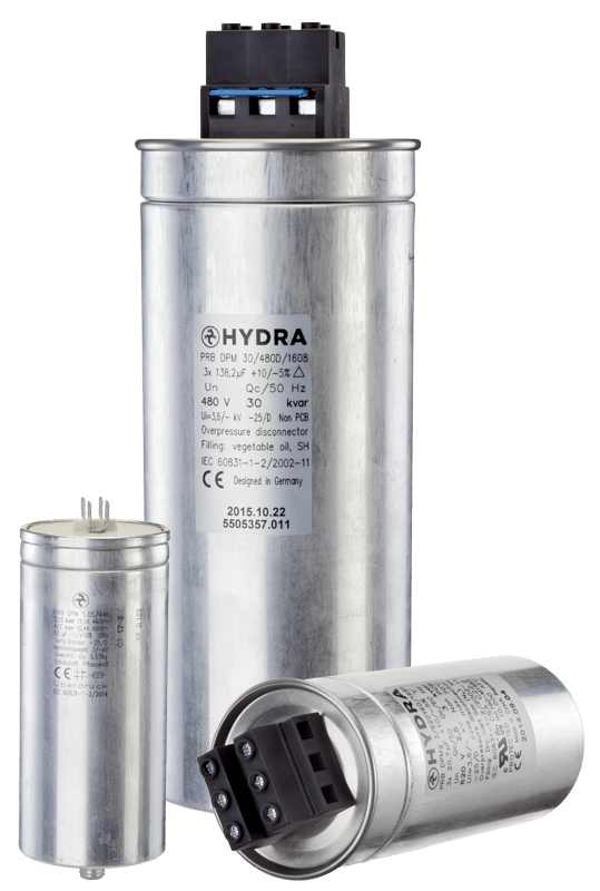
All four HYDRA PFC capacitor series are rated for 50 Hz and 60 Hz and comply with EN/IEC 60831-1/2 and UL 810, according to the HYDRA catalogue 2025. The catalogue gives a permanent overcurrent of 1.3 × In for the PAB and PMB series and 1.5 × In including harmonics for the PRB series. HYDRA filter reactors for detuned banks are listed for 400 V and 525 V, 50 Hz networks with detuning factors of 5.67 %, 7 %, 12.5 % and 14 %, and reactors for other mains voltages and frequencies are available on request.
| Series | Construction | Connection | Rated voltage | Rated output |
|---|---|---|---|---|
| PAB DPM(d) | Oil or soft resin | 1-phase | 230 to 525 V AC | 1 to 6.5 kvar |
| PMB DPM(d) | Gas (N2) filled | 1-phase or 3-phase delta | 230 to 525 V AC | 1 to 6.5 kvar |
| PRB DPMg | Gas (N2) filled | 1-phase or 3-phase, star or delta | 230 to 690 V AC | 5 to 35 kvar |
| PRB DPM(d) | Oil or soft resin | 1-phase or 3-phase, star or delta | 230 to 690 V AC | 5 to 56 kvar |
Further documents:
- HYDRA capacitors catalogue 2025 (PDF), with the full PFC capacitor data and approvals
- Components for power factor correction (PDF): filter reactors, PFC controllers, fuses and capacitor switching contactors
- HYDRA products
- Documents and certificates: ISO 9001, RoHS and REACH
- Contact for 60 Hz ratings and reactors for other network frequencies
References
- IEC 60831-1:2014, Shunt power capacitors of the self-healing type for a.c. systems having a rated voltage up to and including 1 000 V, Part 1: General, Performance, testing and rating, Safety requirements, Guide for installation and operation, edition 3.0. Free IEC preview (Clause 1 Scope, table of contents with clauses 20.1, 21 and 29).
- IEC 60831-2:2014, Part 2: Ageing test, self-healing test and destruction test.
- UL 810, Capacitors, 6th edition (2019, revised 2025), scope 1.3. UL Standards & Engagement.
- OpenStax, University Physics Volume 2, 15.2 Simple AC Circuits (capacitive and inductive reactance) and 15.5 Resonance in an AC Circuit (resonant frequency).
- R. Gallay, Metallized Film Capacitor Lifetime Evaluation and Failure Mode Analysis, CERN Yellow Reports CERN-2015-003, p. 45. doi:10.5170/CERN-2015-003.45, section 2 (high currents, series resistance and loss factor).
- M. Islam, D. Sutanto, K. M. Muttaqi, Protecting PFC capacitors from overvoltage caused by harmonics and system resonance using high temperature superconducting reactors, IEEE Transactions on Applied Superconductivity 29(2), 2019. Abstract, University of Wollongong.
- HYDRA capacitors catalogue 2025 (PDF), PFC capacitors (overcurrent, overvoltage, rated frequency) and HYDRA components for power factor correction (PDF), filter reactors.
Products in this article
Power factor correction
Check stockAsk a HYDRA engineer
Send us your application data and our engineers will help you choose the right film capacitor. HYDRA has made film capacitors since 1899, with production in Jičín (Czech Republic) and Da Nang (Vietnam).
Ask an engineerCheck stock