Does a Capacitor Cut Your Electricity Bill? Power Factor Correction Facts for Modern Loads
In this article
Few questions about capacitors reach a wider audience than this one. The YouTube channel The Electrical Guy asks it in a video titled "Can Capacitor reduce our electricity bill ? Power saver device Real or fake". Capacitor-type power factor correction devices advertised on the internet, which NIST notes are sometimes referred to as "Amp Reduction Units" or "KVARs", suggest exactly that: a device that improves the power factor and lowers a residential electricity bill.
The honest answer depends on who pays the bill and how it is metered. For a household, a capacitor does not reduce the bill. For a commercial or industrial site whose tariff charges for low power factor, reactive energy or kVA demand, power factor correction can reduce the bill. And for sites with a large share of drives and other power electronic loads, capacitors alone cannot bring the power factor close to 1. This article separates the three cases. Sizing at 50 and 60 Hz and detuning against resonance were covered in an earlier article in this series and are not repeated here.
Key takeaways
- For a household, a capacitor does not reduce the bill.
- For a commercial or industrial site whose tariff charges for low power factor, reactive energy or kVA demand, power factor correction can reduce the bill.
- And for sites with a large share of drives and other power electronic loads, capacitors alone cannot bring the power factor close to 1.
Why a household bill does not change
A residential meter registers active energy in kWh. NIST describes the watt-hour meter as monitoring the product of voltage, current, power factor and time. When a capacitor is connected in parallel with an inductive load, the current from the power line falls, but the power factor rises correspondingly, so the product of current, voltage and power factor, and with it the bill, stays essentially the same. NIST reached this conclusion when it examined capacitor-type devices sold for homes: they do not reduce the homeowner's electric bill.
The lower line current does have a benefit, but it accrues upstream of the meter. In the example of the NIST primer, a capacitor matched to a central air conditioner reduced the amplitude of the current drawn from the power line from about 34 A to about 31.3 A, while the current needed by the motor stayed unchanged. The utility then has smaller resistive losses along the power line, which NIST estimates at about 1.80 USD per year for a single residence. NIST also assumes that the capacitor is disconnected when the load is off, because otherwise it would keep drawing current from the line.
Where power factor correction genuinely pays
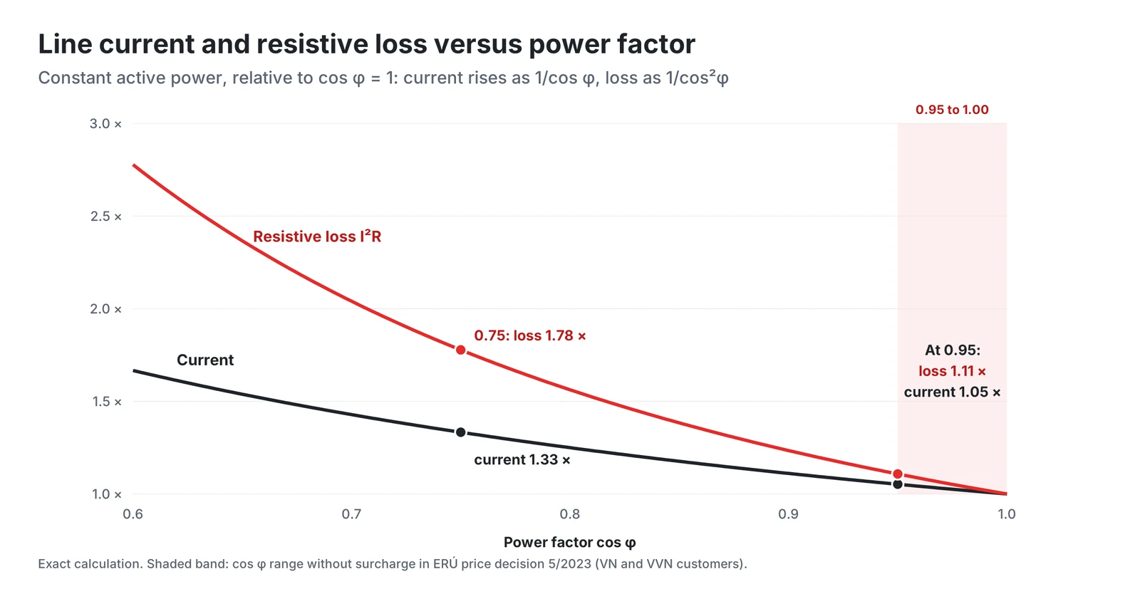
Commercial and industrial tariffs are different because the network operator charges for the reactive part as well. In the Czech Republic, the price notice of the Energy Regulatory Office ERÚ No. 13/2025, valid from 1 January 2026, applies a charge for not maintaining the power factor to customers connected at the VN and VVN voltage levels (point 4.52). The power factor is evaluated from metered inductive reactive energy in kVArh and active energy in kWh as tg φ = kVArh/kWh (point 4.56), and no charge applies while cos φ stays between 0.95 and 1.00 (point 4.58). Below 0.95, a surcharge coefficient from the table in point 4.58 applies: the charge is the coefficient multiplied by the highest quarter-hour demand and the reserved capacity price, plus the coefficient multiplied by the network and energy price and by the energy consumed in the period (point 4.59 and part nine). Over-compensation is not free either: unrequested supply of reactive energy into the distribution network is charged at 440 Kč/MVArh (point 4.60).
Elsewhere the tariff may charge for demand in kVA instead. The South African utility Eskom notes that where a kVA demand clause or another low power factor penalty is part of the tariff, removing reactive power improves the power factor and reduces the bill by minimising the kVA. NIST likewise notes that some utilities charge a penalty for power factors below 0.95, for example for industrial users with large inductive loads.
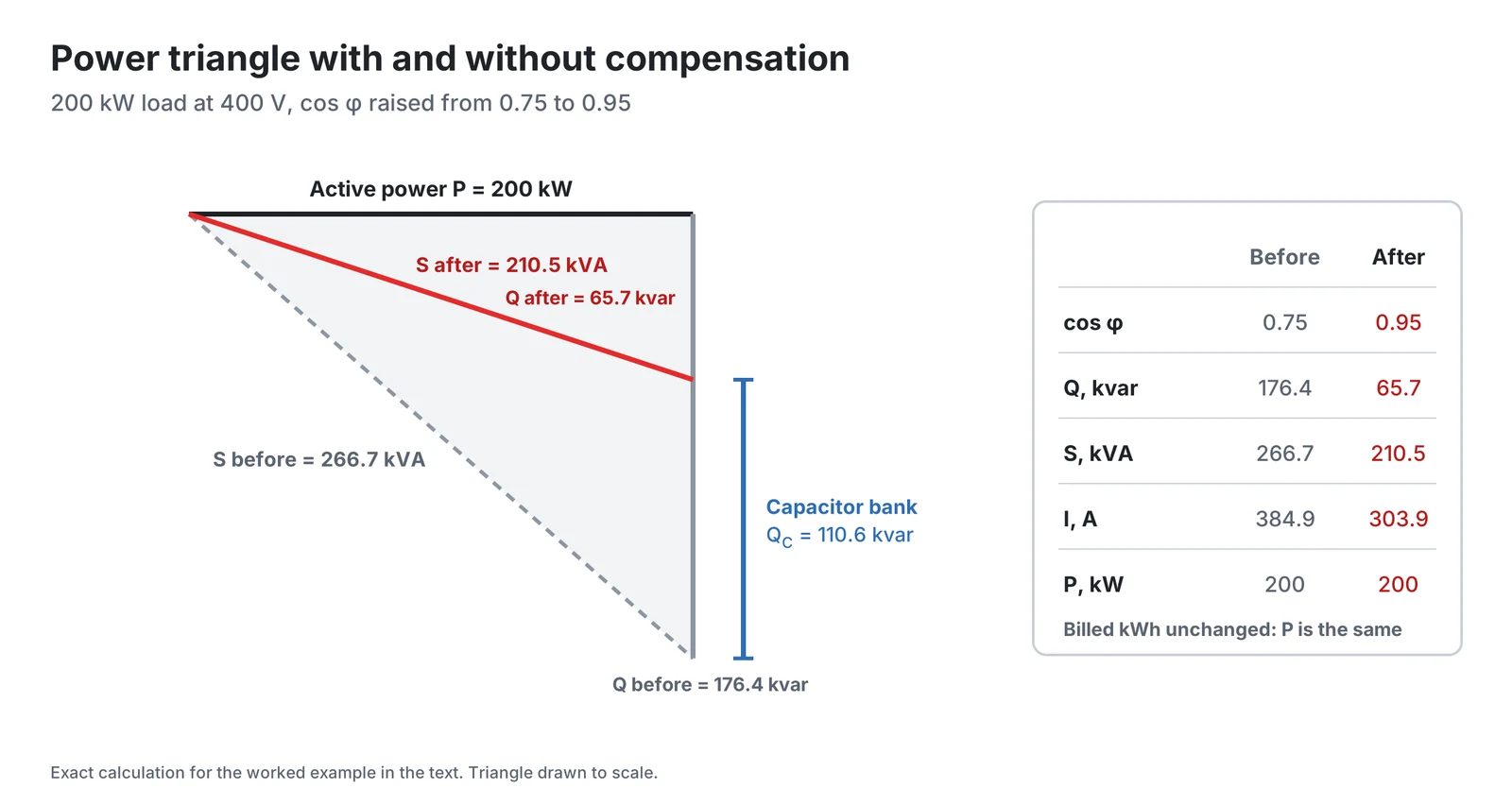
In the power triangle of the US Department of Energy fact sheet on power factor, the power factor is the ratio of real to apparent power and the reactive power acts at 90° to the real power, so Q = P × tan φ. The required capacitor power therefore follows from the active power and the two values of tan φ:
Worked example. A 400 V plant draws 200 kW at cos φ = 0.75. The apparent power is 266.7 kVA and the reactive power 176.4 kvar. To reach cos φ = 0.95, the reactive power must fall to 65.7 kvar, so the bank must supply 110.6 kvar. Apparent power drops to 210.5 kVA.
Lower current, lower losses, released capacity
Besides the tariff, compensation reduces the current in the customer's own transformer, busbars and cables. For constant active power the current is proportional to 1/cos φ, and, as Eskom notes, the losses are proportional to the square of the current. Eskom estimates the reduction of losses as 100 - 100 × (original power factor / improved power factor)² percent. In the example the line current falls from 384.9 A to 303.9 A, by 21 %, and the I²R loss by 1 - (0.75/0.95)² = 38 %.
With an assumed feeder resistance of 10 mΩ per phase, the loss in that feeder falls from 3 × 384.9² × 0.010 = 4.44 kW to 2.77 kW, a saving of 1.67 kW. Over an assumed 4000 operating hours per year this is about 6.7 MWh in one feeder alone, before transformer copper losses are counted. Unlike in the household case, these savings appear on the meter, because they occur downstream of it: as Eskom puts it, lower losses in the distribution system within the facility mean that fewer kilowatt-hours need to be purchased from the utility.
The same arithmetic releases transformer capacity. A 400 kVA transformer loaded with the 200 kW plant runs at 67 % of its rating at cos φ = 0.75 and at 53 % at 0.95. At full rating it could supply 300 kW at the original power factor but 380 kW after compensation, which can postpone a transformer upgrade when a new production line is added. Eskom describes the same effect: the released capacity permits additional loads without overloading the system or paying for a network upgrade.
Modern loads: displacement is not the whole power factor
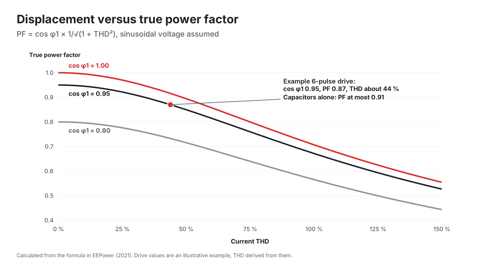
The calculations above assume sinusoidal currents. Many modern loads are non-linear: variable speed drives and other power electronic converters distort the supply current with harmonics, which increases losses and reduces the power factor (Popescu et al.). With a sinusoidal voltage, only the fundamental current component in phase with the voltage contributes to real power, and the MIT lecture on power factor therefore splits the true power factor into a distortion factor and a displacement factor. With THD defined as the RMS of the harmonic content normalised to the RMS of the fundamental, and no DC component, the true power factor is:
Here cos φ₁ is the displacement factor, the reduction caused by the phase shift between voltage and fundamental current, and 1/√(1 + THD²) is the distortion factor, the reduction caused by harmonic currents that carry no real power. Even if cos φ₁ is raised to 1, the true power factor cannot exceed the distortion factor. Take, as an illustrative example, a load with an assumed displacement power factor of 0.95 and a total power factor of 0.87. Solved for THD, these two figures imply a current distortion of about 44 %, and even full displacement correction would leave the power factor at about 0.92. Saleh and Arafa also note that where harmonics are present, power factor correction capacitors can be exposed to resonance, after which protective relays take the capacitors out of service.
When non-linear loads form a significant share of the site load, the choice of equipment changes. In a detuned bank, a filter reactor is connected in series with the capacitors, and its detuning factor sets the resonance frequency of the combination. Saleh and Arafa list, for a 50 Hz network, 189 Hz for a detuning factor of 7 % and 134 Hz for 14 %, both below the 5th harmonic at 250 Hz. Where the distortion itself must be reduced, a shunt active power filter is connected in parallel with the non-linear load and injects a compensating current at the point of common coupling. The review by Popescu et al. describes active power filters as the solution with the best compensation performance for harmonics, reactive power and load unbalance, while classic passive filters are low in cost but bulky and do not adapt to changes in the system.
A short checklist before investing
- Read the tariff: is reactive energy, cos φ or kVA demand billed at the connection point?
- Measure, do not estimate: log kW, kvar, cos φ and current THD over at least a typical production week.
- Separate displacement and distortion. If THD is high, plan a detuned bank or an active filter, not a plain bank.
- Avoid over-compensation at light load, which some tariffs penalise as well.
- Count the internal benefits: cable and transformer losses and spare transformer capacity.
Conclusion
A capacitor does not reduce a household electricity bill, because the meter registers the product of voltage, current and power factor, which does not change when the power factor improves. Capacitor-type power savers therefore sell a physical effect that the household bill does not reward. On commercial and industrial sites the situation is reversed: tariffs such as the Czech rule for cos φ below 0.95 or kVA demand charges make reactive power expensive, and compensation also cuts the current, losses and transformer loading inside the plant. For loads with high current distortion, the displacement power factor is only part of the story, and such sites need detuned banks, used against resonance, or active filters, which compensate the harmonics.
HYDRA manufactures single-phase and three-phase PFC capacitors of metallized polypropylene for rated voltages from 230 to 690 V, filled with oil, soft resin or nitrogen, together with filter reactors, capacitor switching contactors, controllers and fuses for complete banks. The final selection for a specific installation should always be based on measurements and confirmed with the capacitor manufacturer's application engineers.
HYDRA PFC capacitors and documents
All four HYDRA PFC capacitor series are rated for 50 Hz and 60 Hz networks and are intended for fixed compensation, automatic PFC equipment and tuned or detuned banks, according to the HYDRA catalogue 2025.
| Series | Construction | Connection | Rated voltage | Rated output |
|---|---|---|---|---|
| PAB DPM(d) | Oil or soft resin | 1-phase | 230 to 525 V AC | 1 to 6.5 kvar |
| PMB DPM(d) | Gas (N2) filled | 1-phase or 3-phase delta | 230 to 525 V AC | 1 to 6.5 kvar |
| PRB DPMg | Gas (N2) filled | 1-phase or 3-phase, star or delta | 230 to 690 V AC | 5 to 35 kvar |
| PRB DPM(d) | Oil or soft resin | 1-phase or 3-phase, star or delta | 230 to 690 V AC | 5 to 56 kvar |
Further documents:
- HYDRA capacitors catalogue 2025 (PDF), with the full PFC capacitor data
- Components for power factor correction (PDF): filter reactors, PFC controllers, fuses and capacitor switching contactors
- Stock types
- HYDRA products
- Documents and certificates: ISO 9001, RoHS and REACH
- Contact
References
- The Electrical Guy, Can Capacitor reduce our electricity bill ? Power saver device Real or fake, YouTube video, title and channel as retrieved on 18 October 2026.
- NIST, NIST Team Demystifies Utility of Power Factor Correction Devices, news release, 15 December 2009.
- M. Misakian, T. L. Nelson, W. E. Feero, Regarding Electric Energy Savings, Power Factors, and Carbon Footprints: A Primer, NIST Technical Note 1654, October 2009.
- Energetický regulační úřad, Cenový výměr č. 13/2025 ze dne 27. listopadu 2025, kterým se stanovují ceny za související službu v elektroenergetice a ostatní regulované ceny, points 4.52 to 4.60 and part nine, Energetický regulační věstník 17/2025, valid from 1 January 2026.
- Eskom, Power factor: Technical overview, fact sheet, Energy Advisory Service, February 2020.
- US Department of Energy, Motor Challenge, Reducing Power Factor Cost, fact sheet DOE/GO-10096-286.
- D. Perreault, 6.622 Power Electronics, Lecture 4: Power Factor, MIT OpenCourseWare, Spring 2023.
- M. Popescu, A. Bitoleanu, C. V. Suru, M. Linca, L. Alboteanu, Shunt Active Power Filters in Three-Phase, Three-Wire Systems: A Topical Review, Energies 17 (2024) 2867, open access.
- S. M. Saleh, M. E. Arafa, Improving the Power Factor Correction in the Presence of Harmonics by Reducing the Effect of Resonance and Harmonics, Indonesian Journal of Electrical Engineering and Computer Science 3 (2016) 282-295, Table 1.
- HYDRA a.s., HYDRA capacitors catalogue 2025.
- HYDRA a.s., Components for Power Quality: filter reactors, PFC controllers, fuses, capacitor switching contactors (ed. 02/13).
Products in this article
Power factor correction
Check stockAsk a HYDRA engineer
Send us your application data and our engineers will help you choose the right film capacitor. HYDRA has made film capacitors since 1899, with production in Jičín (Czech Republic) and Da Nang (Vietnam).
Ask an engineerCheck stock